GM3 Noise Suppressor v1.0
Contents
Overview
<div class="thumb tright"></div>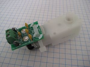
This circuit will suppress electrical noise generated by many small, brushed DC motors. It was designed to fit on the GM3 gearmotor that the RepRap project uses as its extruder motor of choice. This noise suppression helps keep the noise down in the electrical system, where it might cause bad effects (such as reading quadrature signals, i2c signals, etc.) It was primarily based on Nophead's great work.
- You'll need a soldering toolkit to do most of this.
- Read our Electronics Fabrication Guide if you're new.
Get It!
Full Kit
Raw Components
Files
<div class="thumb tright"></div>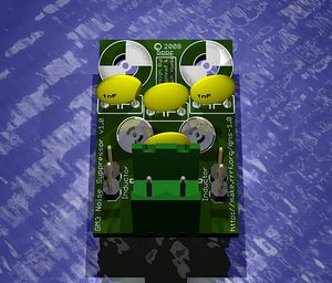
You can download the electronics files from Sourceforge.
This file contains the following:
- GERBER files for getting it manufactured
- PDF files of the schematic, copper layers, and silkscreen
- Eagle source files for modification
- 3D rendered image as well as POVRay scene file
- exerciser code to test your board.
Schematic
<div class="thumb tright"></div>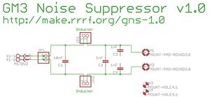
Interface
TODO: add a picture of the positive and negative terminals.
Build It
Board Bugs (listed by version)
- No bugs yet, please report any you find to the forums.
Printed Circuit Board
<div class="thumb tright"></div>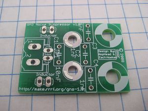
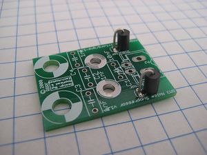
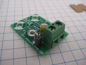
You can either buy this PCB from the RepRap Research Foundation, or you can make your own. The image above shows the professionally manufactured PCB ready for soldering.
Components
<div class="thumb tright"></div>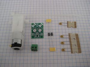
<iframe src="http://parts.reprap.org/embed/module/GM3+Noise+Suppressor+v1.0" width="600" height="360" frameborder="0">Visit http://parts.reprap.org/embed/module/GM3+Noise+Suppressor+v1.0</iframe>
Soldering Instructions
<div class="thumb tright"></div>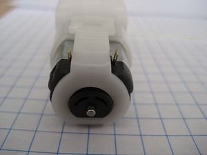
Bend Tabs Up
The first step is to bend the tabs on the motor up so that they will fit in the motor tab holes. Be careful to only bend them once. The metal will fatigue very quickly and if they break off, you're basically out of luck.
Inductors
These guys look like capacitors, but they're not: thats a ferrite cylinder surrounding a wire. Bend the wire 180 degrees, careful not to touch it to the ferrite cylinder. Solder it into place as shown. Orientation is not important.
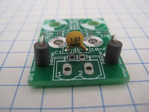
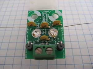
C1 - 10nF
This capacitor should be marked '103'. Solder the capacitor into place. Orientation does not matter.
Screw Terminals
This is where you attach your power wires to the motor. Solder it into place with the wire holes facing outwards.
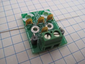
C2, C3, C4 - 1nF
These capacitors should be marked '102'. Insert them and solder them into place. Only clip the inside leads. Leave the outside leads on C3 and C4 intact. Bend them outwards as shown in this picture. We will solder them to the motor body later.
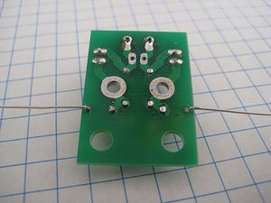
This is a picture of the bottom. Note which leads have not been clipped. Do not clip them!
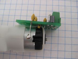
GM3 Gearmotor
This is a slightly tricky part. The two large holes near the center of the board are for soldering the motor to. You will need to use quite a bit of solder. You may also need to have someone hold the board in place (or use tape) while you solder. Once it cools, the board will be attached to the motor. Be careful until you get it more firmly attached.
Motor Body
For extra noise cancellation, we want to solder the legs of the capacitors to the body of the motor. First, bend the leads of the capacitor so that it touches the motor. Cut the lead off a little bit after where it first touches. You'll want to clean the motor surface with rubbing alcohol, as well as apply a bit of flux to it. Once you've done that, then solder the leads to each side. Make sure there is a firm connection.
Zip Tie
There are two holes at the top of the board which you can use to sturdily mount the board to the motor. I like to use a zip tie: simply insert it through each hole, zip it into place and the board is now firmly attached to the motor. Combined with the other 4 solder joints, you now have a very solid attachment, and a very low chance of breaking the tabs on the motor. After you zip tie it down, you may want to re-melt the solder joints on the tabs to relieve any pressure that may have been created.
Use it!
This board is entirely passive, so all you need to do is hook up your motor to your motor driver board just like you would without the noise suppressor. Well,except you have the added benefit of having a built-in screw terminal on the board that will make things really easy for you. Just insert the wires, and screw the terminals down. Bingo!
Good luck!
Further reading
- Nophead's Extruder Tweaks#Interference suppressor links to some o'scope traces that show how bad the noise was without a noise suppressor.