Optischer Grenztaster 2.1
Hinweis: Dies wird die Übersetzung der Seite http://reprap.org/wiki/OptoEndstop_2_1
Contents
Übersicht
<div class="thumb tright"></div>
Die kartesischen (senkrecht aufeinander stehenden) Achsen des RepRaps brauchen alle eine Referenzposition (auch bezeichnet als Home-Position oder End-Halt), um ihre Bewegungen zu referenzieren. At the start of each build each axis needs to back up until the datum point is reached. For RepRap, we use one opto-switch for each axis to define its position. The opto switches also help protect the machine from moving past its intended range and damaging itself.
You will need 3* (three) of these for a basic RepRap machine, and *6 (six) of them for a full machine with both home and end stops.
For those using the ZD1901 opto interrupter prevalent in the Southern Hemisphere, a simple stripboard assembly is required. Details here.
- You'll need a soldering toolkit to do most of this.
- Read our Electronics Fabrication Guide if you're new.
Besorge ihn Dir!
Komplettes Kit
- Full kits (parts + pcb) available from MakerBot Industries
- Opto Endstop RRS-OE Set x3 from RepRapSource
- Buy the board from German RepRap Foundation
Einzelne Komponenten
Dateien
<div class="thumb tright"></div>
You can download the electronics files from Sourceforge.
Diese Datei enthält:
- GERBER-Dateien, um die Platine fertigen zu lassen
- PDF-Dateien mit Schaltplan, Kupferlagen der Platine und Bestückungsaufdruck
- Eagle-Dateien zum Selbständern
- 3D-Bild sowie POVRay-Szene
- Testcode, um Deine Platine testen zu können.
Schaltplan
<div class="thumb tright"></div>
Anschluss
<div class="thumb tright"></div>
Prüf-LED
Die Prüf-LED ist eine optische Anzeige des momentanen Schaltzustands. Bitte beachte: Aufgrund von Beschränkungen der Schaltung ist die LED-Anzeige invertiert im Vergleich zum tatsächlichen Signal. Dies bedeutet, dass wenn der Ausgang auf 1 (high) ist, leuchtet die LED nicht, und wenn der Ausgang auf 0 (low) ist, leuchtet die LED. Siehe die Tabelle unten für mehr Informationen:
Ausgabe
The output of the switch is a binary value that represents the state of the switch. LOW = 0v/GND and HIGH = 5V. The output of the circuit depends on the particular model of opto switch used. RepRap has recently switched from the H21LOI to the H21LOB due to the wider availability of the H21LOB.
The H21LOI and H21LOB are identical, except their outputs are inverted respective to each other. This requires a change in firmware to interpret the input appropriately. Below are truth tables that describe the different outputs the circuits provide.
Wahrheitstabelle für H21LOB
| Status | Ausgabe | LED |
| Offen | HIGH | Aus |
| Geschlossen | LOW | Ein |
Wahrheitstabelle für H21LOI
| Status | Ausgabe | LED |
| Offen | LOW | Ein |
| Geschlossen | HIGH | Aus
|
Physikalischer Anschluss
The v2.x series of Opto Endstop is an experiment in standardization of connectors. One of the major problems with the previous v1.0 design is that it required the end user to construct their own connectors which was a tedious and error prone process. The new v2.x design has 2 different connector footprints: the old .100" spaced connector as well as an RJ45 connector. It is up to the end user to decide which connector they would like to use.
RJ45-Buchse
Bitte sprich mir nach:
Der Opto-Endstopp v2.x unterstützt nicht Ethernet!
Der Opto-Endstopp v2.x unterstützt nicht Ethernet!
Der Opto-Endstopp v2.x unterstützt nicht Ethernet!
What we are doing is hijacking a common and very cheap connector for our own purposes. RJ45 patch cables and jacks are ubiquitous, versatile, robust, and cheap. We've considered and rejected many other connector technologies (RJ11, 3.5mm audio cables, etc) but in the end, RJ45 is the best for our needs. If you have another source of high quality premade cables (that we have not already rejected) please bring it to our attention in the forums. Please do not complain about being forced to use these cables, as there is a simple on-board alternative (see below).
Below you will find a pin out table containing the pin-out information on a standard RJ45 patch cable.
| Pin | Farbe | Funktion |
| 4 und 5 | Blau und Blau/Weiß | 5V-Versorgung |
| 6 | Grün | Signal |
| 7 und 8 | Braun und Braun/Weiß | Ground (= GND = Masse) |
.100" Spaced Header
<div class="thumb tright"></div>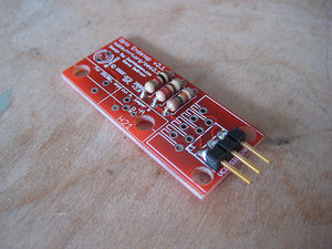
In order to maintain backwards compatibility, as well as giving the user the freedom to chose their desired connector technology, we have included a standard, .100" pitch connector footprint that you may populate as desired. The pins are clearly labeled, and you may wire it however you like. You can solder wires directly to the board, solder in right-angle headers, normal headers, or any other number of technologies. Its up to you as a user to decide. Shown here is an example of using a right-angle .100" spaced header.
Baue ihn
Fehler der Platine (aufgelistet nach Version)
- Bisher keine Fehler, wenn Du welche findest, berichte sie bitte in den Foren.
Platine
<div class="thumb tright"></div>
You can either buy this PCB from the RepRap Research Foundation, or you can make your own. The image above shows the professionally manufactured PCB ready for soldering. Its also cheap, only $0.75 USD.
Komponenten
<div class="thumb tright"></div>
<iframe src="http://www.thingiverse.com/thing:940/partlist" width="500" height="500" frameborder="0"></iframe>
Lötanweisungen
<div class="thumb tright"></div>
R1 - 10K ohm (Brown - Black - Orange)
Insert the resistor in any orientation. Double check the color bands.

R2 - 220 ohm (Red - Red - Brown)
Insert the resistor in any orientation. Double check the color bands.

R3 - 1K ohm (Brown - Black - Red)
Insert the resistor in any orientation. Double check the color bands.

Blocked/Debug LED
The LED must be inserted in the proper orientation. Insert the short leg (negative) into the hole closest to the flat side of the silkscreen.

H21LOB
This is the opto switch. It can only be inserted in one direction. Insert it and solder it info place.
Steckverbinder für Stromversorgung und Signal
<div class="thumb tright"></div>
There are many different types of alternative connectors you could use: You could solder wires directly to the board. You could solder .100" spaced pin headers (both straight and 90 degree), you could solder in a keyed header, or you could solder in female headers. Its all up to you. Shown here is a board with right angle pin headers soldered in. This (or, better, with a straight connector) is how it should be wired for RepRap.

RJ45-Buchse
DIESE PLATINE UNTERSTÜTZT NICHT ETHERNET! This is the MakerBot configuration. We are using the jack to provide simple, easy, cheap connectors.
Insert the jack (it should snap into place) and solder it into place.
Opto-Schalter ZD1901
The board also supports using simpler opto isolators that may be more prevalent in your area (say New Zealand). One such opto switch is the ZD1901 opto switch. This is a 4-pin opto switch and it is relatively easy to hook up. There are actually instructions on the board which we'll illustrate below:
<div class="thumb tright"></div>
Step 1: Cut trace marked 'A'
Cut this trace with an exacto knife, dremel, or other suitable sharp instrument. Take care not to hurt yourself or any of the other traces.

Step 2: Jumper holes marked 'B'
In order to get the signal properly routed, take a small piece of wire and solder it in place as shown to connect the two holes together. You may wish to put the link on the other side of the board to let the ZD1901 sit flush on the board's surface.
Step 3: Solder ZD1901 in place
Solder the ZD1901 in place making sure to insert it in the proper orientation.
Teste ihn
If you are building a RepRap, see here for the opto-switch testing procedure.
<div class="thumb tright"></div>Testing the Opto Switch is very easy: once you have it wired up, all you have to do is block and unblock the opto switch to make sure that it is working. With the integrated LED, this is very easy, as you get a visual indication of the status from the LED. Additonally, you'll want to wire it up to an Arduino or Sanguino to test that the signal is being transmitted successfully.
Schließe ihn an
<div class="thumb tright"></div>
There are a few ways to go about this, mainly determined by what set of electronics you have.
If you are using the RJ45 jack / ethernet cable solution:
If you have one of the new Stepper Motor Drivers (v1.2+, v2.0+) that has an integrated RJ45 jack, then you can simply plug the Opto Endstop to the Stepper Motor Driver, and make sure the Stepper Motor Driver is wired to your Arduino and/or Sanguino. If you do this, make sure that you change the pin definition to the appropriate pin for testing.
If you have an older driver, or want to test it manually, then the easiest way is to cut the end off an old ethernet cable, and connect the exposed wires directly to an Arduino / Sanguino directly. Remember to keep a plug on one end, so you have something to plug into the opto endstop. The advantage of this is that you can use the same cannibalized cable to test all of your opto endstops, as well as all of your temperature sensors. If you're using a standard patch cable, then the wire colors should correspond to the table below:
| Color | Pin |
| Brown | GND |
| Brown/White | GND |
| Green | Signal |
| Blue | VCC |
| Blue/White | VCC |
Note that Brown/White-striped-Brown as well as Blue/White-striped-Blue are both connected to each other. You can use either of them, or solder them together. Your call.
If you are using the .100" spaced headers:
Its up to you! Make sure you know which wires are what, and that you wire the signal wire to the appropriate
Wire it!
Now that you know what wires to use, wire them to the appropriate places:
| Pin | Arduino/Sanguino Pin |
| VCC | 5v |
| Signal | Digital 2 |
| GND | Ground |
Upload sketch!
Here is a sketch to upload to your Arduino or Sanguino that will allow you to test your opto endstop. Make sure you set it to use the right pin, and optionally the right chip if you're using a non-standard board.
//what pin are we using?
#define ENDSTOP_PIN 2

//which opto enstop are we using?
//this is for the H21LOB
#define INVERTED 1
//this is for the H21LOI
//#define INVERTED 0

void setup()
{
   pinMode(ENDSTOP_PIN, INPUT);

   Serial.begin(9600);
   Serial.println("Starting opto endstop exerciser.");
}

void loop()
{
   if (digitalRead(ENDSTOP_PIN))
   {
     if (INVERTED)
       Serial.println("open.");
     else
       Serial.println("blocked.");
   }
   else
   {
     if (INVERTED)
       Serial.println("blocked.");
     else
       Serial.println("open.");
   }

   delay(500);
}
Benutze ihn!
This board is very simple to use: Simply wire it up to your Stepper Motor driver, or wire it directly to your Arduino or Sanguino. When wiring it up for actual use in your RepRap machine, make sure you wire it to the specified pin.
Good luck!
Geschichte
Änderungsprotokoll
- added debug LED
- added support for ZD1901 opto switches
- added RJ45 jack
- added better labels on .100" spacers
- converted to eagle based design
Frühere Versionen
- A bugfix on the Opto Endstop v2.0 (not documented)
- Which was an incremental improvement of the Opto Endstop v1.0