Prusa i3 Hephestos
|
English • العربية • български • català • čeština • Deutsch • Ελληνικά • español • فارسی • français • hrvatski • magyar • italiano • română • 日本語 • 한국어 • lietuvių • Nederlands • norsk • polski • português • русский • Türkçe • українська • 中文(中国大陆) • 中文(台灣) • עברית • azərbaycanca • |
Release status: working

| Description | |
| License | |
| Author | |
| Contributors | |
| Based-on | |
| Categories | |
| CAD Models | |
| External Link |
Contents
- 1 Introduction
- 2 Gallery
- 3 Technical specifications
- 4 Changes with respect to other models Prusa i3
- 5 Printed Parts
- 6 Bill of Materials
- 7 Assembly Guide
- 7.1 Required tools not included in the BOM
- 7.2 Preparation before assembly
- 7.3 Axis assembly
- 7.3.1 X Axis
- 7.3.1.1 Bearing Assembly
- 7.3.1.2 Prepare the X Axis tensioner
- 7.3.1.3 Enter the X Axis tensioner
- 7.3.1.4 Assembly smooth rod bearings
- 7.3.1.5 Prepare the X Axis Endstop sensor
- 7.3.1.6 Introduce the X Axis Endstop sensor in the smooth rod
- 7.3.1.7 Assemble the smooth rod into the side parts
- 7.3.1.8 Mount the X Axis motor
- 7.3.1.9 Introduce the adjustment screw for the X Axis Endstop
- 7.3.1.10 Introduce the pulley on the X Axis motor
- 7.3.2 Z Axis
- 7.3.2.1 Couple the motor hold on the frame
- 7.3.2.2 Couple the Z motors
- 7.3.2.3 Attach the top tether of smooth rods
- 7.3.2.4 Prepare the Z Axis Endstop
- 7.3.2.5 Union X Axis with Z Axis: Insert threaded rods
- 7.3.2.6 Union X Axis with Z Axis: Introduce smooth rod
- 7.3.2.7 Union X Axis with Z Axis: Union with X Axis:
- 7.3.2.8 Union X Axis with Z Axis: Flexible coupling
- 7.3.2.9 Union X Axis with Z Axis: Z Axis Endstop
- 7.3.3 Y Axis
- 7.3.3.1 Preparation of M10 threaded rod
- 7.3.3.2 Preparation of smooth rods
- 7.3.3.3 Union of smooth rods with threaded rods
- 7.3.3.4 Secure with nuts
- 7.3.3.5 Secure with cable ties
- 7.3.3.6 Preparation of Y Axis tensioner
- 7.3.3.7 Preparation of Y Axis motor
- 7.3.3.8 Preparation of the M8 threaded rods - Part 1
- 7.3.3.9 Preparation of the M8 threaded rods - Part 2
- 7.3.3.10 Union of the rods
- 7.3.3.11 Secure the structure with nuts
- 7.3.3.12 Preparation of the aluminum base
- 7.3.3.13 Secure the base aluminum with cable ties
- 7.3.3.14 Prepare the Endstop of the base
- 7.3.3.15 Secure the Endstop at the base
- 7.3.3.16 Place the belt of the Axis Y
- 7.3.3.17 Tighten all nuts
- 7.3.3.18 Place the acrylic base
- 7.3.3.19 Prepare the Y Axis Endstop on the frame
- 7.3.3.20 Secure the Y Axis Endstop on the frame
- 7.3.3.21 Union Y Axis with the X and Z axes: Snap axes
- 7.3.3.22 Union Y Axis with the X and Z axes: Fit and tighten nuts
- 7.3.4 Extruder
- 7.3.4.1 Prepare the carriage
- 7.3.4.2 Place the carriage in the X axis
- 7.3.4.3 Secure the carriage with a flange
- 7.3.4.4 Place the belt on the X Axis
- 7.3.4.5 Screw the Extruder support
- 7.3.4.6 Place the extruder
- 7.3.4.7 Placing the blower nozzle and Hot end security
- 7.3.4.8 Place the glass on the base
- 7.3.5 Electronic
- 7.3.6 Tuck the wires in the X Axis chain stitch
- 7.3.1 X Axis
- 7.4 Printer settings
- 7.5 Hello world: Your first print
- 7.6 Annex
Introduction
Facilitate the installation and set-up of the printer.
- Prusa 3D printer Hephestos is an open source 3D printer designed and developed by the bq Department of Innovation and Robotics. Hephestos is based on the Prusa i3 and adds several improvements to other printers like PowerCode. Parts were developed by the RepRap community with modifications and new parts added by bq.
- This project has sought to offer a robust printer design, addressing many of the shortcomings of earlier designs such as end-stop positioning and wiring routing. We have placed particular emphasis on providing good documentation to facilitate its assembly.
- Where to buy
 - bq Spain - (author) - free shipment
 - Leds & Chips Assembled - Portugal
 - Leds & Chips Portugal
 - Iniciativas 3D Spain
 - wi3d Print Spain
 - 3D Proditive Shop Spain
 - Simac Spain
 - Crea3D Italy
 - 3DPrinter Store Ch

Building Instructions Video (Youtube):
<videoflash type="youtube">nvTeJvRi8Bo</videoflash>
Prusa i3: Unboxing video (Youtube):
<videoflash type="youtube">c_TUTrBQ2XU</videoflash>
Gallery


Technical specifications
Dimensions
- -Printer Dimensions: 460(X) x 370(Y) x 510 mm(Z without roll) 583 mm(Z with roll )
- -Print Area Dimensions: 215(X) x 210(Y) x 180 mm(Z)
- -Box Dimensions: 400(X) x 400(Y) x 250 mm(Z)
Mechanical Construction
- -Powder coated aluminium frame & base
- -Smooth chrome rods for bearing carriages X, Y, Z
- -Linear ball bearing LM8UU for X, Y, Z
- -Axial ball bearing pulleys B623ZZ for X, Y
- -Igus cable carrier chain
- -Flexible aluminium coupling for threaded rods of Z Axis
- -4 point print base levelling system with cushioning
- -Quick change system for print base with Clips
- -Brushless Fans with axial ball bearings.
Print resolution
- -Very high: 60 microns
- -High 100 microns
- -Medium 200 microns
- -Low 300 microns
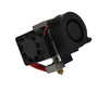
Extruder Mechanics
- -Custom extruder design (Witbox)
- -0.4mm nozzle
- -Fin heatsinks with axial fan
- -Part cooling nozzle
Print speed
- -Recommended speed: 50 mm / s
- -Maximum recommended speed: 80 mm / s
Electronics
- Any RepRap electronics conforming to RepRap Interface Standard RIS 1.
- -LCD with rotary encoder and push-button navigation
- -Cold glass base (size:220 x 220 x 3 mm)
- -Power supply: 220 AC 12 DC 100W
- -Thermistor 100k extruder
- -Heating element: 12V 40W
Software
- -Firmware derivative Marlin
- -Recommended environment: Cura Software
- -Supported Files:. Gcode
- -OS supported:
- Windows XP and above
- Mac OS X and above
- Linux
Communications
- -Standard SD card reader
- -USB Port Type B
Materials
- PLA Filament 1.75-mm
Changes with respect to other models Prusa i3
- Limit switch clamping:
- Designed by the department specifically for this model.
- Limit switch clamping:
- Belt tensioners
- Tensioner X axis identical to the Power Code. Tensioner Axis Ydownloaded from Thingiverse. http://www.thingiverse.com/thing:68185
- Support for RAMPS
- Designed by the department specifically for this model. Includes three anchors to collect the wires on one side through the use of a cable tie. Guiding the cables ensures the Driver heatsinks are not covered.
- Support LCD
- Designed by the department specifically for this model. The design has been inspired by http://www.thingiverse.com/thing:121640
- Support Fan
- Designed by the department specifically for this model.
- Cable Carrier
- Parts modified to include the cable carrier on all axis, avoiding pinching, cuts and catching the cable during axis movement.
- Power supply
- Laptop power supply
- Extruder
- Witbox extruder.
- Frame
- Official Prusa design modified. A recess has been added to the Y axis area to prevent friction which previously existed during the levelling of the base plate caused by the screw protruding. File:Frame&base Hephestos.dxf.zip
- Printing volume
- 215x210x180 mm
Printed Parts
Thingiverse page: http://www.thingiverse.com/thing:371842
Own designs
X Axis cable carrier coupling
Part Downloads 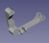
File:Acople cadeneta Eje X.zip

Mechanical Endstop clamping X axis
Part Downloads
File:EjeX final de carrera.zip

Mechanical Endstop clamping Y axis
Parts Downloads 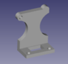
File:EjeY final carrera marco.zip 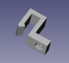
File:EjeY final carrera base.zip


Mechanical Endstop clamping Z axis
Part Downloads 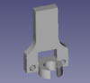
File:Eje Z final carrera.zip

Hot End security
Part Downloads 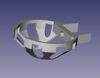
File:Seguridad Hot end.zip

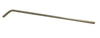
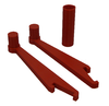
Tools
Part Downloads 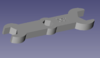
File:Llave fija impresa archivos.zip

LCD support
Part Downloads 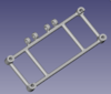
File:Soporte lcd.stl 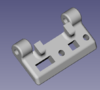
File:Bisagra lcd.stl


Fan support
Part Downloads 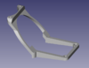
File:Soporte ventilador archivos.zip

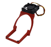
Filament holder


Modified
X Axis carriage
- The following changes have been made to the original carriage:
- -Attachment to rewind Igus cable carrier at the top (above the bearings).
- -Addition of a small cap to ensure contact with the limit of X axis (on the side, next to the linear bearing carriage below)
Original Modified X Axis carriage (PowerCode) X Axis carriage (Hephestos) 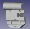
File:Eje X carro A archcivos.zip


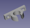
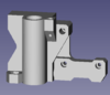
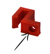
Left side motor mounting for Z-Axis
- -Incorporated coupling for cable carrier.
Original Modified Left side motor mounting for Z-Axis (PowerCode) Left side motor mounting for Z-Axis (Hephestos) 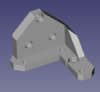
File:I3-zbottom izq.stl File:Eje Z soporte inferior izquierda archivos.zip


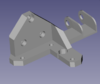
End of the X Axis motor
- Added support material to the screw which adjusts the Z axis height.
- -The base has been elongated to reduced the clearance of the nut thereby preventing the screw from moving.
- -The screw hole has been shifted outwards to improve accuracy in the mechanical Endstop activation.
Original Modified X Axis left (PowerCode) X Axis left (Hephestos) 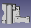
File:EjeX izquierda.zip
.PNG)
.PNG)
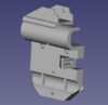
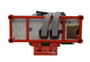
RAMPS support
- Added three hooks. Each hook works by using cable ties to hold and collect all the cables connected to the RAMPS. By guiding the cables through the side and into the plate at the top left corner it facilitates cooling of drivers by not having cables directly above the heat sinks.
Original Modified RAMPS support (Witbox) RAMPS support (Hephestos) 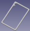
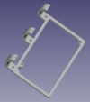
File:Suplemento RAMPS(original).stl File:Soporte RAMPS archivos.zip


Complete Kit
Complete Part Kit for Hephestos:
Bill of Materials
Tools
Part Name Quantity Description
Allen key s/long Ø 2 UNIOR Ø 2 mm 1 - 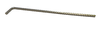
Allen key s/long Ø 2.5 mm 1 - 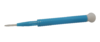
Ceramic screw driver trimmer for electronics. 1 Screwdriver for adjusting the current of the motor drivers step by step, bipolar Nema 17 and extruder. 
Precision Needle 0.4mm diameter 2 Required for maintaining the Hotend and removing blockages. 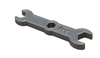
Printed spanner 10 (M6) - 13 (M8) - 17 (M10) 1 Printed spanner for nuts M6, M8 & M10 (corresponds to spanner size 10, 13, & 17)

Electronics
Part Name Quantity Description
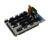
Ramps 1.4 1 Freaduino Mega 2560 v1.2. Design based on Arduino Mega 2560 + Ramps 1.4, with heatsink on the MOSFET of the hot bed. 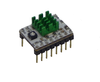
Stepstick Drivers A4988 4 Stepstick Drivers A4988 with 4 layers and improved heat dissipation to avoid overheating & heatsinks for attached drivers. 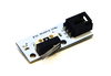
Endstop 3 Endstop mounted on PCB with LED indicator. 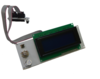
LCD control panel 1 LCD control panel with card reader for automatic printing (SD card not included) and 30 cm cables. 
USB cable (type B), 1.8 m. 1 Standard USB cable with male connectors (type A & B) 1.8 meters long. 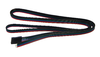
Motor wire Nema 17 4 4 strand cable for bipolar stepping motor Nema 17 (2.5A 1.8deg/step) with female connector. 
Endstop wire 40 cm 2 3 strand cable for Endstop with female click connector (3pins) 40 cm long. Endstop wire 85 cm 1 3 strand cable for Endstop with female click connector (3pins) 85 cm long. 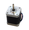
Motor Nema 17 4 Bipolar stepping motor Nema 17 (2.5A 1.8deg/step) 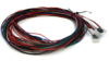
Wiring kit for extruder (Motor wire Nema (with connector) + Thermistor wire with connector + Fan and blower wire + Heater cartridge) 1 Wiring kit for extruder (4 strand cable for bipolar stepping motor Nema 17 (2.5A 1.8deg/step) with connector JST XHP-6 & female 4 pin connector + 2 strand cable for extruder thermistor with female 2 pin connector + Crimped fan and blower wire with terminal sleeve + Cartridge heater cable with terminal sleeve. 
150 mm of flexible wire with two bicolor strands with cross section of 1 mm² 1 150 mm of flexible wire with two bicolor strands with cross section of 1 mm². 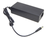
Power supply 220 AC 12 DC 100W 1 Power supply with 1.10m cable, 100 W with 2.1mm connector Jack INPUT: 100-240VAC 1,8A 50-60Hz & OUTPUT: 12 VDC 8.0A). 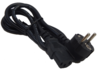
Power Supply Cable (European) 1 Cable of 1,10m for 220V AC with Schuko connector (Male) & IEC-60320-C13 connector (Female). 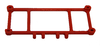
Printed support for lcd 1 Support to locate the LCD on the top part of the aluminium frame. Custom design. 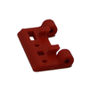
Printed hinge for lcd support 1 Hinge for the LCD support located on the top part of the aluminium frame. Custom design. 
Printed support for ramps 1 Support for isolating the electronics from the aluminium frame. Used in conjunction with 3 cable ties to organise the wiring. Custom design. 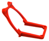
Printed fan support 1 Support for 50x50mm fan. Located above the electronics to prevent overheating. Custom design. 
M3x10 Screw - DIN-912 Class 8.8 Black 4 - 
M3x12 Screw - DIN-912 Class 8.8 Black 2 - 
M3x16 Screw - DIN-912 Class 8.8 Black 2 - 
M3x20 Screw - DIN-912 Class 8.8 Black 4 - 
M3 Nut - DIN 934 Class 8 Black 12 - 
Heat shrink tube 2.5 x 500 mm 1 - 
Black cable tie 100 x 2.5 mm 10 - 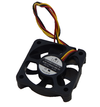
Brushless DC Cooling Fan - RD5010B12H with 20cm wire without connector 1 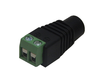
Adapter/connector Jack-Ramps 1 Adaptor/connector Jack, 2.1mm, female with Ramps 1.4 2 terminal header. 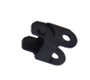
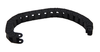
Plastic cable carrier chain link Igus 52 Link for constructing Igus cable carrier 045.10.018 (external measurements: 15 x 10mm)


Extruder
Part Name Quantity
Witbox Extruder ( direct extruder for 1.75 mm filament, with 0.4mm nozzle) 1 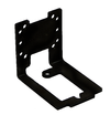
Extruder support 1 
Hot End safety guard (Hephestos) 1 
M4 x 6mm Screw DIN-912 8.8 Class (with head for Allen 2.5mm) 2 M3x10 Screw - DIN-912 8.8 Class Black 2 M3 x16 Screw - DIN-912 8.8 Class Black 1 M3 Nut - DIN 934 Class 8 Black 1


X Axis
Part Name Quantity
Chromed smooth rod 8mm x 370mm 2 M3x10 Screw - DIN-912 8.8 Class Black 4 M3x16 Screw - DIN-912 8.8 Class Black 2 M3x20 Screw - DIN-912 8.8 Class Black 2 
M3x25 Screw - DIN-912 8.8 Class Black 1 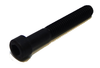
M6x40 Screw - DIN-912 8.8 Class Black 1 M3 Nut - DIN 934 Class 8 Black 7 
M5 Nut - DIN 934 Class 8 Black 2 
M6 Nut - DIN 934 Class 8 Black 3 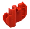
X Axis Carriage A PowerCode modified 1 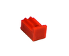
X Axis Carriage B PowerCode 1 
X Axis B623ZZ bearing Pulley PowerCode 2 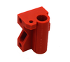
X Axis Right PowerCode 1 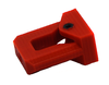
X Axis tensioner B623ZZ bearingPowerCode 1 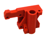
X Axis leftPowerCode Modified 1 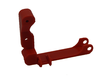
X Axis left thread chain coupling PowerCode 1 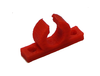
X Axis Endstop (Hephestos) 1 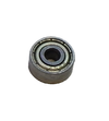
B623ZZ axial bearing 1 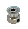
GT2 pulley (20 theet) 1 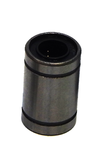
LM8UU Linear bearing 1 Black cable tie 100x2.5mm 1


Y Axis
Part Name Quantity
Chromed smooth rod 8mm x 340mm 2 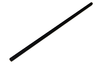
Black threaded rod M10x370mm 2 Black threaded rod M8 x 205mm 4 M3 x10 Screw - DIN-912 8.8 Class Black 7 M3 x16 Screw - DIN-912 8.8 Class Black 1 M3 x20 Screw - DIN-912 8.8 Class Black 1 M3 x25 Screw - DIN-912 8.8 Class Black 6 M3 Nut - DIN 934 Class 8 Black 7 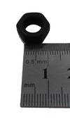
M8 Nut - DIN 934 Class 8 Black 22 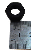
M10 Nut - DIN 934 Class 8 Black 8 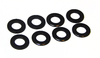
M8 Washer - DIN-125 Class 6 Black 22 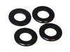
M10 Washer - DIN-125 Class 6 Black 8 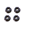
M10 serrated Nut - DIN 6923 Class 8 Black 4 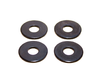
M10 Washer - DIN-125 Class 6 Black 4 Y Axis B623ZZ bearing Pulley 2 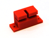
Y Axis belt holder. Prusa 1 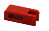
Y Axis tensioner B623ZZ bearing http://www.thingiverse.com/thing:68185 1 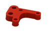
Y Axis motor PowerCode 1 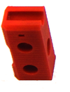
Y Axis Corner PowerCode 1 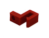
Y Axis base Endstop (Hephestos) 1 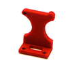
Y Axis frame Endstop (Hephestos) 1 GT2 pulley (20 teeth) 1 LM8UU Linear bearing 3 Black cable tie 100x2.5mm 11 
GT2 belt 6mmx1m 1 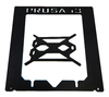
Aluminium base 1 
Acrylic base 220x220x8mm holes 3.5mm 1 B623ZZ axial bearing 1 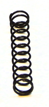
Spring (long: 30,5mm ; Outside diameter: 4,5mm; Wire thickness: 0.45mm) 4 
Glass Plate 220x220x3mm 1 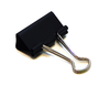
Black Binder Clip (35x10mm) 4 Black cable tie 100x2.5mm 11


.png)
Z Axis
Part Name Quantity Chromed smooth rod 8mm x 320mm 2 Black threaded rod M5x300mm 2 M3x10 Screw - DIN-912 8.8 Class Black 16 
M3 x18 Screw - DIN-912 8.8 Class Black 2 M3 Nut - DIN 934 Class 8 Black 2 
Z Axis top support PowerCode 1 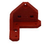
Z Axis bottom right support PowerCode 1 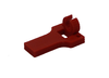
Z Axis Endstop (Hephestos) 1 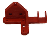
Z Axis bottom left support PowerCode modified 1 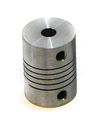
Flexible coupling aluminium 5 to 5 mm 2 Black aluminium frame 1


Assembly Guide
Required tools not included in the BOM
Part Picture 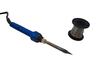
Solder Iron and Solder 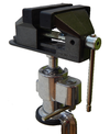
Vice 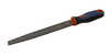
Metal file 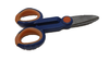
Scissors


Preparation before assembly
Prepare pulleys
- Materials Needed:
Part Name Quantity LM8UU Linear bearing 1 X and Y Axis Pulley bearing B623ZZ 2
- Assembly:

Step A

Step B

Step C

Step D
Preparation of the motors
- Materials Needed:
Part Name Quantity Motor Nema 17 4 Metal file 1 Vice 1
- Assembly:

Step A

Step B

Step C
Embed nuts
- Materials Needed:
Picure Name 
Solder Iron Part - Nut

- Assembly:

Step A

Step B

Step C

Step D

Step E

Step F
- Parts to be embed with nut:
Picture Detail Picture Name Nut Quantity 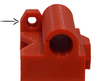
X Axis Right M5 Nut - DIN 934 Class 8 Black 1 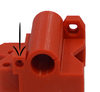
X Axis left M3 Nut - DIN 934 Class 8 Black 1 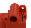
X Axis left M5 Nut - DIN 934 Class 8 Black 1 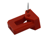
X Axis tensioner B623ZZ bearing M3 Nut - DIN 934 Class 8 Black 1 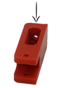
Y Axis tensioner B623ZZ bearing M3 Nut - DIN 934 Class 8 Black 1 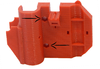
X Axis Carriage A M3 Nut - DIN 934 Class 8 Black 2 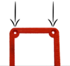
Fan support M3 Nut - DIN 934 Class 8 Black 2 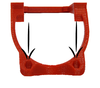
Fan support M3 Nut - DIN 934 Class 8 Black 2 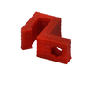
Y Axis base Endstop M3 Nut - DIN 934 Class 8 Black 1 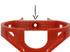
Hot End Safety Guard M3 Nut - DIN 934 Class 8 Black 1


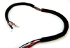
Preparation of motor cables
- Materials Needed:
Picture Name Quantity Motor Nema 17 4 Motor Nema wire 17 4 Solder Iron and Solder 1 Heat shrink tube 2.5 x 500 mm 1
- Cable length (from base of engine to end of connector)
Motor Total length (cm) Motor length (cm) Extesnion lenght(cm) X 85 30 55 Y 50 20 30 Z Right 45 15 30 Z Left 65 30 35
- Note: Cut four parts of the heat shrink tubing for the Motor wire to 2cm long.
- Note: Prepare motors of X and Y axis before mounting the engines, and the Prusa Z Axis, after mounting.
- Assembly:

Step A

Step B

Step C

Step D

Step E

Step F

Step G

Step H

Step I

Step J
- Note: Before soldering the cables of Z axis motors, pass the bare wire through the motor hole.
- Assembly:

Step A

Step B
Power supply cable preparation
- Materials Needed:
Picture Name Quantity Scissors 1 Adapter/connector Jack-Ramps 1 Power supply 220 AC 12 DC 100W 1 150 mm flexible 2 colour wire (1 mm²) 1
- Assembly:

Step A

Step B

Step C

Step D

Step E
Step F

Step G
Axis assembly
X Axis
Bearing Assembly
- Materials Needed:
Part Name Quantity LM8UU Linear bearing 4 X Axis left 1 X Axis Right 1
- Assembly:

Step A

Step B

Step C
Prepare the X Axis tensioner
- Materials Needed:
Part Name Quantity X Axis tensioner B623ZZ bearing 1 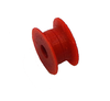
Pulley 1 M3x20 Screw - DIN-912 8.8 Class Black 1 M6x40 Screw - DIN-912 8.8 Class Black 1
- Assembly:

Step A

Step B

Step C

Step D
Enter the X Axis tensioner
- Materials Needed:
Part Name Quantity 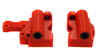
Assembly step 1 1 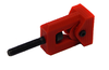
Assembly step 2 1 M6 Nut - DIN 934 Class 8 Black 3
- The objective of the tensioner is to load or unload a belt easily once set.
- Note: It is necessary to sand/file the parts. The tensioner should slide perfectly into the part that holds it.
- Assembly:

Step A

Step B

Step C
- Note: The two nuts at the end are to be tightened together. Use a nut wrench on the adjacent nut to assist. This way you can ensure that the nuts are securely fitted to the screw. Now by using the wrench as shown in the picture, crank the tensioner to the side to achieve the required tension when fitting the belt.

Step D

Step E

Step F
- Note: Use the nut wrench when fitting and tightening the nuts on the screw.
Assembly smooth rod bearings
- Materials Needed:
Part Name Quantity Chromed smooth rod Ø 8mm x 370mm 2 LM8UU Linear bearing 3
- Assembly:
Step A
Step B
Prepare the X Axis Endstop sensor
- Materials Needed:
Part Name Quantity X Axis Endstop 1 Endstop 1 M3 Nut - DIN 934 Class 8 Black 2 M3x10 Screw - DIN-912 8.8 Class Black 2
- Assembly:

Step A

Step B
Introduce the X Axis Endstop sensor in the smooth rod
- Materials Needed:
Part Name Quantity 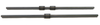
Assembly step 4 1 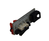
Assembly step 5 1
- Assembly:
Step A

Step B
Assemble the smooth rod into the side parts
- Materials Needed:
Part Name Quantity Assembly step 1 1 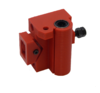
Assembly step 3 1 Assembly step 6 2
- Assembly:
- The length of the rod between the side parts (when assembled) should be approximately 31 cm.
Step A
Step B
Mount the X Axis motor
- Materials Needed:
Part Name Quantity Motor Nema 17 1 M3x10 Screw - DIN-912 8.8 Class Black 2 M3x16 Screw - DIN-912 8.8 Class Black 2 
Assembly step 7 1 X Axis left thread chain coupling 1
- Assembly:
- Note: Orient the motor cable from the top.

Step A

Step B

Step C
Introduce the adjustment screw for the X Axis Endstop
- Materials Needed:
Part Name Quantity 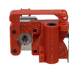
Assembly step 8 8 M3x25 Screw - DIN-912 8.8 Class Black 1
- Assembly:

Step A

Step B
Introduce the pulley on the X Axis motor
- Materials Needed:
Part Name Quantity Motor Nema 17 1 GT2 pulley (20 theet) 1
- Assembly:
- Note: Use the 2mm Allen wrench to tighten the pulley to the motor axis by the chamfered area.

Step A

Step B

Step C
Z Axis
Couple the motor hold on the frame
- Materials Needed:
Part Name Quantity Z Axis right bottom support 1 Z Axis left bottom support 1 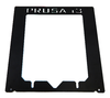
Black aluminum frame 1 M3x10 Screw - DIN-912 8.8 Class Black 6

- Assembly:

Step A

Step B
Couple the Z motors
- Materials Needed:
Part Name Quantity Motor Nema 17 2 
Assembly step 1 1 M3x10 Screw - DIN-912 8.8 Class Black 6
- Assembly:
Note: Orient the motor cable to the frame

Step A
Step B
Attach the top tether of smooth rods
- Materials Needed:
Part Name Quantity Black aluminum frame 1 Z Axis top support 2 M3x10 Screw - DIN-912 8.8 Class Black 2 M3x18 Screw - DIN-912 8.8 Class Black 2
- Assembly:
Note: It is necessary to sand the parts.
Step A
Step B
Prepare the Z Axis Endstop
- Materials Needed:
Part Name Quantity Endstop 1 Z Axis Endstop 1 M3x10 Screw - DIN-912 8.8 Class Black 2 M3 Nut - DIN 934 Class 8 Black 2
- Assembly:

Step A

Step B

Step C
Union X Axis with Z Axis: Insert threaded rods
- Materials Needed:
Part Name Quantity 
X Axis 1 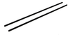
Z Axis Endstop 1

- Assembly:

Step A

Step B
Union X Axis with Z Axis: Introduce smooth rod
- Materials Needed:
Part Name Quantity 

Assembly step 2 and 3 1 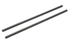
Chromed smooth rod 8mm x 320mm 2

- Assembly:

Step A

Step B
Union X Axis with Z Axis: Union with X Axis:
- Materials Needed:
Part Name Quantity 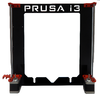
Assembly step 6 1 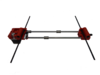
Assembly step 5 1
- Assembly:

Step A

Step B

Step C
Union X Axis with Z Axis: Flexible coupling
- Materials Needed:
Part Name Quantity 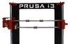
Assembly step 7 1 Flexible coupling aluminum 5 to 5 mm 2
- Assembly:
Step A
Step B

Step C

Step D
Union X Axis with Z Axis: Z Axis Endstop
- Materials Needed:
Part Name Quantity Assembly step 8 1 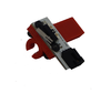
Assembly step 4 1
- Assembly:
- Note: Paste with adhesive for plastics the step assembly 4 to the motor bracket.

Step A

Step B
Y Axis
Preparation of M10 threaded rod
- Materials Needed:
Part Name Quantity Black threaded rod M10x370mm 2 M10 Nut - DIN 934 Class 8 Black 4 M10 Washer - DIN-125 Class 6 Black 4 M10 Washer -(Ø 30 mm) DIN-9021 Black 4 M10 Nut - DIN 934 Class 8 Black 4
- Assembly:
Step A
Step B
Preparation of smooth rods
- Materials Needed:
Part Name Quantity Chromed smooth rod Ø 8mm x 340mm 2 LM8UU Linear bearing 3
- Assembly:
Step A
Step B
Union of smooth rods with threaded rods
- Materials Needed:
Part Name Quantity Y Axis Corner 4 
Assembly step 1 1 
Assembly step 2 1
- Assembly:
Step A
Step B
Secure with nuts
- Materials Needed:
Part Name Quantity M10 Nut - DIN 934 Class 8 Black 4 M10 Washer - DIN-125 Class 6 Black 4
- Assembly:
Step A
Step B

Step C
Secure with cable ties
- Materials Needed:
Part Name Quantity 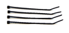
Black cable tie 100x2.5mm 4
- Assembly:

Step A

Step B

Step C
Preparation of Y Axis tensioner
- Materials Needed:
Part Name Quantity Pulley 1 Y Axis tensor B623ZZ bearing 1 M3 x20 Screw - DIN-912 8.8 Class Black 1 M3 x25 Screw - DIN-912 8.8 Class Black 1 M3 Nut - DIN 934 Class 8 Black 2
- Assembly:
Note: The 25 mm screw is used as shaft for the pulley and the 20mm screw for the tensioner.

Step A

Step B
Preparation of Y Axis motor
- Materials Needed:
Part Name Quantity Motor Nema 17 1 Y Axis motor mount 1 M3 x10 Screw - DIN-912 8.8 Class Black 3
- Assembly:

Step A

Step B
Preparation of the M8 threaded rods - Part 1
- Materials Needed:
Part Name Quantity Black threaded rod M8 x 205mm 4 M8 Washer - DIN-125 Class 6 Black 6 M8 Nut - DIN 934 Class 8 Black 6 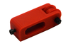
Assembly step 6 1 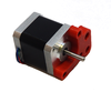
Assembly step 7 1
- Assembly:

Step A

Step B
Preparation of the M8 threaded rods - Part 2
- Materials Needed:
Part Name Quantity M8 Washer - DIN-125 Class 6 Black 8 M8 Nut - DIN 934 Class 8 Black 8 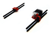
Assembly step 8 1
- Assembly:

Step A

Step B
Union of the rods
- Materials Needed:
Part Name Quantity 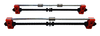
Assembly step 5 1 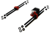
Assembly step 9 1
- Assembly:

Step A

Step B
Secure the structure with nuts
- Materials Needed:
Part Name Quantity M8 Nut - DIN 934 Class 8 Black 8 M8 Washer - DIN-125 Class 6 Black 8 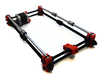
Assembly step 10 1
- Assembly:

Step A

Step B

Step B
Preparation of the aluminum base
- Materials Needed:
Part Name Quantity 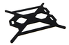
Aluminum base 1 Y Axis belt holder 1 M3 x10 Screw - DIN-912 8.8 Class Black 2

- Assembly:

Step A

Step B
Secure the base aluminum with cable ties
- Materials Needed:
Part Name Quantity 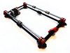
Assembly step 11 1 
Assembly step 12 1 Black cable tie 100x2.5mm 3
- Assembly:

Step A

Step B

Step C

Step D

Step E

Step F

Step G

Step H
Prepare the Endstop of the base
- Materials Needed:
Part Name Quantity Y Axis Endstop 1 M3 x25 Screw - DIN-912 8.8 Class Black 1
- Assembly:

Step A

Step B
Secure the Endstop at the base
- Materials Needed:
Part Name Quantity 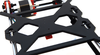
Assembly step 13 1 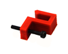
Assembly step 14 1
- Assembly:

Step A

Step B

Step C

Step D
Place the belt of the Axis Y
- Materials Needed:
Part Name Quantity GT2 belt 6mmx1m 1 GT2 pulley (20 theet) 1 Black cable tie 100 x 2.5 mm 4
- Assembly:
- Note: Turn the set
- Note: Tighten pulley with 2mm Allen wrench

Step A

Step B

Step C

Step D
- Note: Screw out screw to slacken the tensioner

Step E

Step F

Step G

Step H

Step I

Step J

Step K

Step L
- Note: Align belt

Step M

Step N

Step Ñ

Step O
- Note: Tighten the belt tensioner bolt tightening
Tighten all nuts
- Materials Needed:
Part Name Quantity Printed spanner 10 (M6) - 13 (M8) - 17 (M10) 1
- Assembly:
- Note: It is necessary to file the burrs.

Step A
Place the acrylic base
- Materials Needed:
Part Name Quantity Acrylic base 220x220x8mm holes 3.5mm 1 M3 x25 Screw - DIN-912 8.8 Class Black 4 Spring (long: 30,5mm ; Outside diameter: 4,5mm; Wire thickness: 0.45mm) 4
- Assembly:
- Note: It is necessary to file the burrs.

Step A

Step B
Prepare the Y Axis Endstop on the frame
- Materials Needed:
Part Name Quantity Y Axis Endstop 1 Endstop 1 M3x10 Screw - DIN-912 8.8 Class Black 2 M3 Nut - DIN 934 Class 8 Black 2
- Assembly:

Step A

Step B
Secure the Y Axis Endstop on the frame
- Materials Needed:
Part Name Quantity 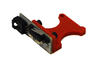
Assembly step 19 1 Black aluminum frame 1 M3x16 Screw - DIN-912 Class 8.8 Black 1 M3 Nut - DIN 934 Class 8 Black 1
- Assembly:

Step A

Step B

Step C

Step D
Step E
Union Y Axis with the X and Z axes: Snap axes
- Materials Needed:
Part Name Quantity 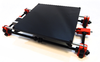
Y Axis 1 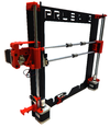
XZ Axis 1

- Assembly:

Step A

Step B

Step C
Union Y Axis with the X and Z axes: Fit and tighten nuts
- Materials Needed:
Part Name Quantity 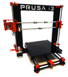
Assembly step21 1 Printed spanner 10 (M6) - 13 (M8) - 17 (M10) 1
- Assembly:

Step A
Extruder
Prepare the carriage
- Materials Needed:
Part Name Quantity X Axis Carriage A 1 X Axis Carriage B 1 M3x20 Screw - DIN-912 8.8 Class Black 1 M3 Nut - DIN 934 Class 8 Black 1
- Assembly:

Step A

Step B
Place the carriage in the X axis
- Materials Needed:
Part Name Quantity 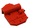
Step assembly 1 1 Prusa 1
- Assembly:

Step A

Step B

Step C

Step D
Secure the carriage with a flange
- Materials Needed:
Part Name Quantity 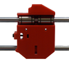
Step assembly 2 1 Black bridle 100 x 2.5 mm 1
- Assembly:

Step A

Step B

Step C

Step D

Step E
Place the belt on the X Axis
- Materials Needed:
Part Name Quantity GT2 belt 6mmx1m 1 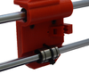
Step assembly 3 1 Black bridle 100 x 2.5 mm 4
- Assembly:

Step A

Step B

Step C

Step D

Step E

Step F
Screw the Extruder support
- Materials Needed:
Part Name Quantity Extruder support 1 M3x10 Screw - DIN-912 8.8 Class Black 2
- Assembly:

Step A

Step B
Place the extruder
- Materials Needed:
Part Name Quantity Witbox Extruder 1 M4 x 6mm Screw DIN-912 8.8 Class (with head for Allen 2.5mm) 2
- Assembly:
- Note: This step is necessary to remove the nozzle of the extruder.
- Nota: Secure with screws the Extruder.

Step A

Step B

Step C
Placing the blower nozzle and Hot end security
- Materials Needed:
Part Name Quantity M3 x20 Screw - DIN-912 8.8 Class Black 1 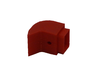
Blower nozzle of the Witbox extruder 1 Hot End security 1

- Assembly:
- Nota: The Hot end security is a opcional complement and no necessary for the correct printer working, but its use is highly recommended to avoid burns.

Step A

Step B

Step C
Place the glass on the base
- Materials Needed:
Part Name Quantity Glass 220x220x3mm 1 Black Biinder Clip (35x10mm) 4
- Assembly:

Step A

Step B

Step C
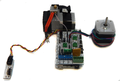
Electronic
Place the RAMPS 1.4
- Materials Needed:
Part Name Quantity
Ramps 1.4 1 M3x20 Screw - DIN-912 Class 8.8 Black 2 Printed support for ramps 1
- Assembly:

Step A

Step B

Step C
Prepare the LCD control panel
- Materials Needed:
Part Name Quantity
LCD control panel 1 Printed support for lcd 2 Printed hinge for lcd 1 M3x10 Screw - DIN-912 Class 8.8 Black 4 M3x20 Screw - DIN-912 Class 8.8 Black 2
- Assembly:

Step A

Step B

Step C

Step D
Mount the LCD control panel on the frame
- Materials Needed:
Part Name Quantity
Assembly step 2 1 M3 Nut - DIN 934 Class 8 Black 2
- Assembly:

Step A

Step B

Step C
Tuck the wires in the X Axis chain stitch
- Materials Needed:
Part Name Quantity
25 roller chain 1 27 roller chain 1 Kit wiring extruder (Nema motor wire (with connector) + Thermistor wire + Fan and blower wiring + Heat cartdridge wire) 1

- Assembly:
- Note: Introduce the wires singly

Step A

Step B

Step C

Step D
Place the X Axis chain stitch
- Materials Needed:
Part Name Quantity
Cadeneta Eje X con cables 1
- Assembly:
- Note: The 25 shackle chain stitch link the X Axis carriage with the X Axis left.
Step A

Step B

Step C

Step D

Step E

Step F
Introduce the Z Axis wires in to the Z Axis chain stitch.
- Materials Needed:
Part Name Quantity 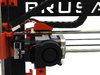
Assembly step 5 1 EndStop wire with click and female connector 85 cm 1
- Assembly:
- Note: Introduce in to the Z Axis chain stitch the X Axis motor and Endstop wires.

Step A

Step B
- Note: The 27 shackle chain stitch link the X Axis left with the Z Axis left bottom support.

Step C

Step D

Step E
Prepare the fan
- Materials Needed:
Part Name Quantity
Fan 50 x 50 mm 1 Printed support for fan 1 M3 x16 Screw - DIN-912 8.8 Class Black 2
- Assembly:

Step A

Step B
Wiring and cable routing
Cable connection diagram

- Materials Needed:
Part Name Quantity
Black bridle 100 x 2.5 mm 11 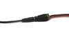
Power supply wire 1 EndStop wire with click and female connector 40 cm 2
Extruder wiring

Step A

Step B

Step C
- Note: Use a flange with the extruder wires.

Step D

Step E
Motors cable routing
- Note: Use a flange with the motors wires.

Step A

Step B
Endstop cable routing

Step A

Step B

Step C
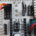
RAMPS Wiring and cable routing
- Note: Use the flanges with the wires.

Step A

Step B

Step C
- Note: Guide the cables through the printed part that holds the RAMPS and secure them with the flanges.
- Note: Connect the clamp plate the fan cables and power supply.

Step D

Step E

Step F
Place the fan
- Materials Needed:
Part Name Quantity
Assembly step 8 1 M3x12 Screw - DIN-912 Class 8.8 Black 2
- Assembly:
- Note: Disconnect the LCD panel control Ramps before placing the fan and pass it through the hole in the workpiece.

Step A

Step B

Step C
Placement the filament holder
- Materials Needed:
Part Name Quantity
Filament holder 1

- Assembly:
- Note: Disconnect the LCD control panel of Ramps before placing the fan and pass it through the hole in the workpiece.

Step A

Step B

Step C
Printer settings
Z Axis adjustment
- Before printing with your printer you must calibrate the screw that adjusts the height of the Z axis so that the extruder is to the correct height of the base. To do this, follow these steps:
- -Put the same height ends of the X Axis. Thread each axis manually until both are at the same height.

Step A
- -Tighten the set screw everything without possible forcing the printer part.

Step B
- -Use the LCD control panel to bring the extruder to home.
- Control > Move Axis > Auto home

Step C

Step D
- Note: Make sure that the Endstops are being touching correctly by their respective axes.
- -Adjusts the position of the endstop sensor adjustment screw and repeat the previous step (bringing the Z axis to home).

Step E
- -If the adjustment isn't correct, repeat the previous step.

Step F
Level plate
- Once Z Axis is adjusted, is necessary level the plate.
- Using the LCD control panel, start the leveling program.
- Control > Level plate
- The program moves the extruder at four points of the base, where you must adjust the screws on each corner, so that you can pass a sheet between the extruder nozzle and glass. Must feel the friction produced by the extruder in the paper passing therebetween.

Step A

Step B

Step C
Step D
Extruder obstruction
- If a blockage occurs in the extruder, follow the next step:
- You must hate the extruder at 220 ° C and insert the 0.4mm needle into the nozzle until you see it come out the other end. After you must clean the needle of adhered plastic.
- If a blockage occurs in the extruder, follow the next step:

Step A
Hello world: Your first print
- If you followed all steps of this manual, you should have your Prusa i3 Hephestos ready to do his first print!
- First you must laminate the 3D design. The 3D designs must be in .stl. For this, you can follow our guides for some used programs.
- Slic3r guide: https://www-cdn.bq.com/file/Witbox/Manual_Slic3r_ES.pdf
- Repetier-Host guide: https://www-cdn.bq.com/file/Witbox/Manual_Repetier_ES.pdf
- Cura 3D guide: https://www-cdn.bq.com/file/Witbox/Manual_Cura_ESP.pdf
- Note: Remember that Prusa i3 Hephestos area is 215x210x180 mm.
- Once you have the g-code file, save the file in a SD card. Insert the SD card in the LCD control panel slot. In main menu select "Print from SD". Now select your g-code file. The printer will start automatically. You can view the progress of the part and the extrusion temperature from the LCD panel of the printer. When printing is completed remove the glass base by removing the clamps. With the base resting on a glass table parts removed by pulling them tight.
- You need apply lac on the glass for the correct adhesion of parts!
Annex
Firmware load
For load a new firmware follow the next steps:
1. Donwload the firmware. In RepRap wiki you can find a entire list of available firmwares:
Link: http://reprap.org/wiki/List_of_Firmware
2. Here are some of the most popular firmwares and our modification of Marlin:
       Marlin: http://reprap.org/wiki/Marlin
       Sprinter: http://reprap.org/wiki/Sprinter
       Marlin Hephestos: File:Marlin Hephestos.zip
3. Download and install Arduino software from main site:
Link: http://www.arduino.cc/en/Main/Software
4. Inside of firmware folder, you must open .ino file with the Arduini IDE.
5. Once open, will appear one tab called "configuration.h". In this file you can configurate the params of your printer.
6. When you complete configuration, load program into Arduino Mega.
Drivers calibration
Materials Needed
| Part | Name | Quantity |
|---|---|---|
 |
Motor Nema 17 | 2 |
 |
Endstop | 1 |
 |
Witbox Extruder | 1 |
 |
Ramps 1.4 | 1 |
 |
Power supply 220 AC 12 DC 100W | 1 |
 |
Multimeter | 1 |
| |
Ceramic screw trimmer f | 1 |
 |
Clema | 1 |
 |
Cable USB tipy B de 1.8 meters | 1 |
| - | Computer with Pronterface | 1 |
This step must be repeat with all drivers, you will need two motors for Z Axis driver calibration.
Intensity for each Driver
| Driver | Intensity (mA) |
|---|---|
| X Axis | 250 |
| Y Axis | 250 |
| Z Axis | 450 |
| Extruder | 680 |
| Arduino with RAMPS | aprox. 74 (no regulable) |

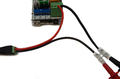
Wiring
Is necessary connect one endstop sensor and thermistor, because of firmware firewalls.
Step A
Step B


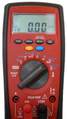
Multimeter preparation
Connect the multimeter in serial connection between Arduino and power supply. Put multimeter in intensity measurement mode.
Step A
Step B


Multimeter adjustment
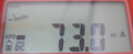
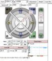
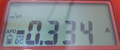
Connect Arduino Mega to computer. The flowing current is 74 mA aprox. (this may differ between plates). Open Pronterface, select the correct port and connect to Arduino.
You must move the motor using Pronterface interface. Measure the current and regulate this using the Ceramic screw trimmer together with the mulitmeter. The current should be set to the sum of the current circulating in the PCBA and the current in the motor. For example, in X Axis current must be 74 mA + 250 mA = 324 mA.
Pre-heat or send the M302 command for completing the extruder calibration.
Arduino needs to be reset before calibrating the next driver.
Step A
Step B
Step C
Step D


Pronterface donwload link: http://reprap.org/wiki/Printrun