RAMPS 1.4.4
Release status: Prototype

| Description | RepRap Arduino Mega Pololu Shield
Arduino MEGA based modular RepRap electronics.
|
| License | |
| Author | |
| Contributors | |
| Based-on | |
| Categories | |
| CAD Models | |
| External Link |
Contents
Summary
A RAMPS shield that can be used with:
- 8-bit or 32-bit controllers
- a single 12V or 24V power supply.
- TMC2130 drivers via SPI bus jumper selection.
And:
- on-board 3V->5V buffer chip, for a higher Gate voltage control for all mosfets
- two additional Fan mosfets. For a total of 3 PWM controlled Fans. With 3x 2.54mm jumper pins for Fan connections (max 1A per fan)
- power selection for Fans: 24V or 12V rails
- SMD mosfets. (datasheet numbers: 2 milli Ohm for Heated Bed, 4 milli Ohm for Hot-end) Max 1A for Fans.
- 'on-board' 24V-to-12V DC-DC switch mode regulator
- a 4-pin 7.62 mm (20A) Screw Terminal Power Connector, for Power Supply and Heat Bed connections
- a "blue" 5.08 (13A) Screw Terminal Connector for Heat-Bed connection
- jumper selection of 12V -> Vin on the Arduino. No soldering of D1 needed.
Further additions are:
- 24V protection on Thermistor inputs
- 100nF capacitors on end-stop pins.
- 5V protection on end-stops - even for 3V controllers
- a high voltage (12V) Z-probe port. Connected to either Z-Min (default) or Z-Max end-stop pins
- Hardware SPI port (at center of board) for use with the Arduino DUE controller
- includes all RAMPS familiar Aux ports - like: Aux-1, Aux-2, Aux-3 (with extensions), Aux-4, Servo, PS-on, I2C, 6x End-stops, 3x Thermistors
- jumper connections for 5V, 12V, 24V. In addition to the usual +Voltage (Vcc pins) on the Aux ports.
And some options:
- for use with a 5V PT100 sense amplifier - even on 3V controllers
- an on-board Resistor option. For experimenting with Thermistor self heating issues
- on-board diodes, which can be used to lower Vin voltage, and help prevent overheating of the Arduino Mega 5V voltage regulator
- an option for an on-board 24LS256 EEPROM. For use with controllers that have no built-in EEPROM.
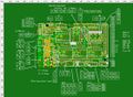
Aux and Pins
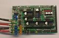
Board
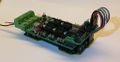
Test fitting an early version on a Re-ARM controller


Click any image for larger versions
How this board came into existence
While I was designing the RAMPS 1.7 shield, a friend said: Well, that is all good and dandy, but 10x10 cm is too big for my printer. I need a RAMPS shield that can do:
- TMC2130 drivers (without SPI wires floating on-top),
- can be used with a single 24V power supply,
- and still be only the size of a standard RAMPS board - or it will not fit nicely on my printer.
And this shield is what we have ended up designing, over several experimental iterations.
Files
Once we have a working prototype, we will share the design files.
Schematics

PDF version here
Motherboard/Controller board options
Arduino Mega
Works as is. And uses the same settings are the same as RAMPS 1.4 shield, with the following exceptions:
- PS-on, is controlled by pin D39.
- And is firmware 'Active High' (because of the additional "open collector" mosfet used to actually do the pull-down of the 'Power On' pin of an ATX styler power supply.
- Where the RAMPS 1.4 signal is firmware 'Active Low', in order to turn on an ATX style power supply.
- Fan 0 is still D9
- Fan 1 is D7
- Fan 2 is D12
CS pins for TMC2130 drivers are all connected to Aux-4, on pins that are NOT being used for the RRD LCD displays. This leaves all pins on Aux-1, Aux-2, Aux-3 and Servo available for regular use.
The TMC2130 CS pins are as follows:
- CsX = D47
- CsY = D45
- CsZ = D32
- CsE0 = D22
- CsE1 = D43
Firmware - Marlin
In file 'configuration.h', select the following:
- For the line MOTHERBOARD, select (or type) "#define MOTHERBOARD BOARD_RAMPS_14_EFB"
- For regular Z-Min use, make sure that the line 'Z_MIN_PROBE_USES_Z_MIN_ENDSTOP_PIN' is uncommented (no // in front of the line)
For Marlin 2.0.x, in file: 'configuration_adv.h' possibly do the following changes
- #define X_CS_PIN 47
- #define Y_CS_PIN 45
- #define Z_CS_PIN 32
- #define E0_CS_PIN 22
- #define E1_CS_PIN 42
- #define E0_AUTO_FAN_PIN 7
For Marlin 1.0.x, in file 'pins_RAMPS_14.h' possibly do the following changes:
- If using the PS_ON_PIN, change it from 12 to 39
- If using TMC2139 stepper driver, with SPI control, then set the corresponding numbers
- For X change from 53 to 47
- For Y change from 49 to 45
- For Z change from 40 to 32
- For E0 change from 42 to 22
- For E1 change from 44 to 43