Gen7 Endstop 1.3.1
|
English • العربية • български • català • čeština • Deutsch • Ελληνικά • español • فارسی • français • hrvatski • magyar • italiano • română • 日本語 • 한국어 • lietuvių • Nederlands • norsk • polski • português • русский • Türkçe • українська • 中文(中国大陆) • 中文(台灣) • עברית • azərbaycanca • |
Release status: working

| Description | Part of Generation 7 Electronics
|
| License | GPL v2
|
| Author | |
| Contributors | |
| Based-on | [[]]
|
| Categories | |
| CAD Models | |
| External Link | (none)
|
Contents
How to get it
Assembled Boards
Get Gen7 Endstops from [1] in the assembled boards category.
PCBs
Get Gen7 Endstop PCBs from Traumflug.
As Gen7 is designed to be manufactured on a RepRap or by other DIY methods, you can make PCBs yourself, of course.
Yet another way is to purchase from one of the many houses specialized in manufacturing prototype PCBs. Gen7 is single sided, so this won't cost a fortune.
Electronic components
Get Gen7 Endstop Components Kits from Traumflug.
If you want to assemble the collection yourself, see the #Parts List section.
Parts List
| Name | Count | Designations | Vendors | Remarks | |||||
|---|---|---|---|---|---|---|---|---|---|
| Resistor 180 Ohms | 1 | R1 | Reichelt | Völkner | Farnell | RS | Digi-Key | Mouser | |
| Resistor 1 kOhms | 1 | R2 | Reichelt | Völkner | Farnell | RS | Digi-Key | Mouser | |
| Resistor 2.2 kOhms | 1 | R3 | Reichelt | Völkner | Farnell | RS | Digi-Key | Mouser | |
| LED 3 mm Red | 1 | LED1 | Reichelt | Völkner | Farnell | RS | Digi-Key | Mouser | |
| Photointerrupter TCST1103 | 1 | U1 | Reichelt | Farnell | RS | Digi-Key | Mouser | This one is without mounting flange. | |
| Alternative Photointerrupter TCST2103 | 1 | U1 | Reichelt | Völkner | Farnell | RS | Digi-Key | Mouser | This one has a mounting flange which might help mounting. |
| Molex KK100 3 Pin Header | 1 | CONN1 | Reichelt | Farnell | RS | Digi-Key | Mouser | Reichelt are tested to be fully compatible with Molex | |
| Cable Connector for the above | 1 | Reichelt | Farnell | RS | Digi-Key | Mouser | |||
| Crimp Contact for the above | 3 | Reichelt | Farnell | RS | Digi-Key | Mouser | |||
Assembly Instructions
- To find out which components to put where, have the layout on your PC screen available.
- PCBs fabricated with Voronoi paths need more heat, so raise your soldering iron's temperature by about 20 deg Celsius.
- Start with the flattest parts, usually wire bridges or resistors. This way, components won't fall out when you lay the PCB on it's front for soldering. Then continue with parts of raising height, connectors are usually among the last ones.
- To ease soldering jumper headers and similar components, put a small drop of cyanacrylate glue onto the component side before inserting them. As the PCB is single-sided, this won't hurt the solder point.
- Take care to not overheat the photo sensor. Solder one pin on each side then pause for a minute before continuing.
- As LEDs have to be inserted the right way they have legs of different length to indicate polarity. The longer leg (+) goes into the hole closer to the photo sensor and the shorter one (-) into the hole closer to the border.
Assembly in Pictures
Click on the pictures to view them bigger.
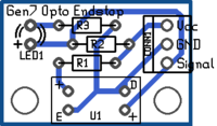
If you're unsure, always refer to this picture of the layout. The designators match those in the parts list.
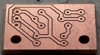
This is the bare PCB. Milled with the traditional, non-voronoi method.
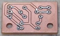
For best solder quality, tin all solder points before inserting components.
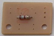
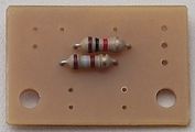
First, insert and solder R1, which is 180 ohms, so it's color-coded brown-grey-brown.
Now R2, which is brown-black-red.
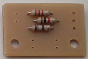
R3 is red-red-red.
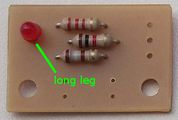
Because it matters which direction LEDs are inserted, they have legs of different length. The longer leg is +, which is inserted closer to the mouting holes.
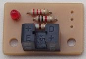
Now insert the light barrier. Watch out for the letters on the housing, they should be readable from the mounting hole side. Solder one pin on the left, then one on the right, then make a pause of a minute before fixing the remaining ones.
Last, insert the cable header. Again, direction matters.


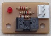
Now we're done, these pictures show the work of StevBrennan:


Assembly on Veroboard in Pictures
If you don't want to etch or buy an endstop board, here is a veroboard version.
Click on the pictures to view them bigger.
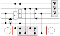
A drawing of the Gen7 Endstop 1.3 Veroboard Version. Cut the tracks at the red lines. Each cross on the squared paper coresponds to a hole in the veroboard. The designators match those in the parts list.
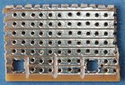
This is the bottom of the veroboard. Mounting holes are already drilled and tracks are cut in the middle under the light barrier. Tracks are also cut towards the mounting holes for preventing shorts because of the mounting screws.
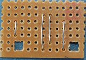
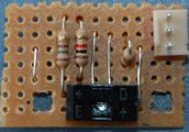
Start with the wire bridges, because two will be under the light barrier. Use some left over component legs.
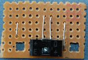
Now insert the light barrier. It will sit atop of the left two wire bridges. Watch out for the letters on the housing, they should be readable from the mounting hole side. Solder one pin on the left, then one on the right, then make a pause of a minute before fixing the remaining ones.
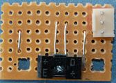
Insert the cable header. Mind the direction. Pins face to the border of the bord.
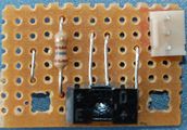
Insert and solder R1, which is 180 ohms, so it's color-coded brown-grey-brown.
R3 is red-red-red. Mount it standing, for minimizing the size of the veroboard.
R2, which is brown-black-red.
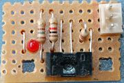
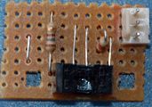
Because it matters which direction LEDs are inserted, they have legs of different length. The longer leg is +, which is inserted closer to the mouting holes.


Setup
TBD