Arduino Breakout v1.2
Depreciated. Use Arduino Breakout v1.3 instead.
Arduino Breakout Shield v1.2
Overview
The Arduino Breakout Shield is a shield that plugs into an Arduino and provides all the Arduino pins as screw terminals. It is perfect for semi-permanent Arduino projects, or just general prototyping. It provides access to all the Arduino pins, as well as providing extra GND, 3.3v, 5v, and Supply voltage pins for convenience.
<div class="thumb tright"></div>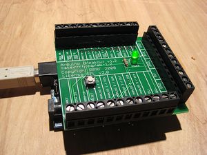
- You'll need a soldering toolkit to do most of this.
- Read our Electronics Fabrication Guide if you're new.
Get It!
Full Kit
Raw Components
Files
You can download the electronics files from Sourceforge.
This file contains the following:
- GERBER files for getting it manufactured
- PDF files of the schematic, copper layers, and silkscreen
- Eagle source files for modification
- 3D rendered image as well as POVRay scene file
- exerciser code to test your board.
Schematic
<div class="thumb tright"></div>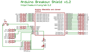
Interface
<div class="thumb tright"></div>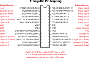
The pins map exactly to the regular Arduino pins. See the reference on the Arduino site for more information.
It also provides multiple outputs for the power pins, which helps when hooking up multiple devices.
There is a reset button located on the shield which will reset your Arduino when pressed, as well as a power-on LED that indicates that your Arduino is powered up.
Build It
Board Bugs (listed by version)
- No bugs yet, please report any you find to the forums.
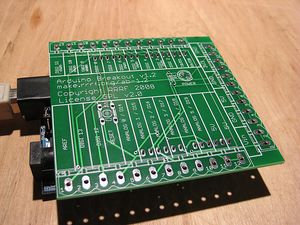
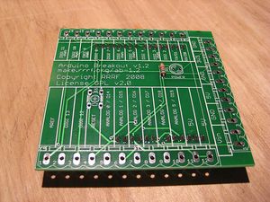
Printed Circuit Board
<div class="thumb tright"></div>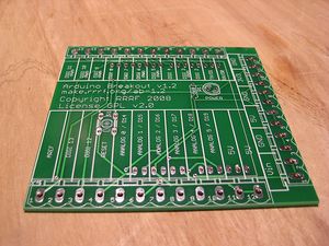
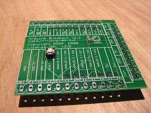
You can either buy this PCB from the RepRap Research Foundation, or you can make your own. The image above shows the professionally manufactured PCB ready for soldering. Its also cheap, only $7.50 USD.
Components
<div class="thumb tright"></div>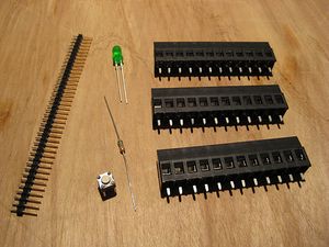
<iframe src="http://parts.reprap.org/embed/module/Arduino+Breakout+v1.2" width="600" height="400" frameborder="0">Visit http://parts.reprap.org/embed/module/Arduino+Breakout+v1.2</iframe>
Soldering Instructions
<div class="thumb tright"></div>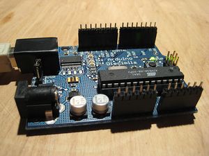
Prepare Arduino Pins
Insert the long ends of the pins into the Arduino. This will allow us to make a perfectly-fitting Arduino shield.
Solder Arduino Pins
Place the board so that the short end of the pins stick through all the holes. Solder it into place.
R1
Take the board off the Arduino to solder the resistor. It can be inserted in any orientation.
BUTTON
You can insert the button in any orientation. It snaps into place for easy soldering.
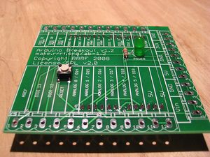
POWER
LEDs have polarity and must be inserted in the right orientation. Line up the flat side of the LED with the flat part of the circle on the silkscreen. If your LED has no flat, the short leg goes into the hole nearest the flat.
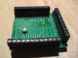
Screw Terminals
All 3 sets of terminals are the same size. Make sure the openings are facing outside.
Test It
<div class="thumb tright"></div>Now that you have your Arduino shield tested, you'll want to test it. Plug your Arduino into a computer, and if the POWER LED comes on, then you're good!
Use it!
You can wire up anything you like to the breakout board and use it for semi-permanent things (like driving a RepRap machine)