RAMPS 1.4.4
Release status: Prototype

| Description | RepRap Arduino Mega Pololu Shield
Arduino MEGA based modular RepRap electronics.
|
| License | |
| Author | |
| Contributors | |
| Based-on | |
| Categories | |
| CAD Models | |
| External Link |
Contents
Summary
The RAMPS 1.4.4 shield is a RAMPS-1.4-pin-compatible shield that can be used with:
- 8-bit or 32-bit controllers
- a single 12V or 24V power supply.
- TMC2130 drivers via SPI bus jumper selection.
And:
- On-board 3V -> 5V buffer chip, for a higher Gate voltage control of all mosfets
- Two additional Fan mosfets. For a total of 3 PWM controlled Fans. With 3x 2.54mm jumper pins for Fan connections (max 1A per fan)
- Power selection for Fans:
- Fan0: power from 24V or 12V rails
- Fan1+2: power as Fan0, or from on-board optional 5V DC-DC switch mode power supply module
- SMD mosfets. (datasheet numbers: 1.65 milli Ohm for Heated Bed, 3.3 milli Ohm for Hot-end) Max 1A for Fans.
- 'on-board' 24V-to-12V DC-DC switch mode module
- A 4-pin 7.62 mm (20A) Screw Terminal Power Connector, for Power Supply and Heat Bed connections
- A "blue" 5.08 (13A) Screw Terminal Connector for Heat-Bed connection
- Jumper selection of 12V (or 8.5V) -> Vin on the Arduino. No soldering of D1 needed.
Further additions are:
- 24V protection on Thermistor inputs
- 100nF capacitors on end-stop pins.
- 12V protection on end-stops
- A high voltage (12V) Z-probe port. Connected to either Z-Min (default) or Z-Max end-stop pins
- Hardware SPI port (at center of board) for use with the Arduino DUE controller
- Includes all RAMPS familiar Aux ports - like: Aux-1, Aux-2, Aux-3 (with extensions), Aux-4, Servo, PS-on, I2C, 6x End-stops, 3x Thermistors
- Jumper connection access to 5V, 8.5V, 12V, 24V rails. In addition to the usual +Voltage (Vcc pins) on the Aux ports.
And some extra options:
- Easy use with a 5V PT100 sense amplifier - even on 3V controllers
- An on-board Resistor option. For experimenting with Thermistor self heating issues
- Lower voltage to Vin (to help prevent overheating of the Arduino Mega 5V volt regulator)
- either via on-board diodes (lower the Vin Volt by about 1V per diode), or
- via an on-board DC-DC 8.5V module
- Optional on-board 24LS256 EEPROM. For use with controllers that have no built-in EEPROM.
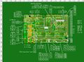
Aux and Pins
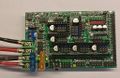
Board
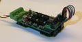
Test fitting an early version on a Re-ARM controller


Click any image for larger versions
How this board came into existence
While I was designing the RAMPS 1.7 shield, a friend said: Well, that is all good and dandy, but 10x10 cm is too big for my printer. I need a RAMPS shield that can do:
- TMC2130 drivers (without SPI wires floating on-top),
- can be used with a single 24V power supply,
- and still only be the size of a standard RAMPS board - or it will not fit nicely on my printer.
And this RAMPS 1.4.4 shield is what we have ended up designing, over several experimental iterations.
Files
Once we have a working prototype, we will share the design files.
For now, various files are available at GitHub
If you are interested in being a part of the early-adopters/testers team, then please send me an email to [email protected]
It is also possible to participate in the RepRap forum discussion here The first 4-5 pages of the forum thread are about the RAMPS 1.7 design, but after that, the focus is moved to this RAMPS 1.4.4 design.
Schematics

PDF version here
Reverse Polarity - just DO NOT do it!!!

|
Do NOT reverse polarity on the power connector. There is NO PROTECTION DIODE for the mosfet's. Reversing polarity is likely to fry your electronics. |
Stepper driver Jumper settings
Under each stepper driver is a set of jumper options.
By setting the jumpers, it is possible to use the standard driver chips, like A4988 and DRV8825 chips (and others) or it is possible to connect the SPI bus signals, to TMC2130 stepper drivers.
A4988 etc.

TMC2130 and TMC5160

Learn more about the TMC2130/TMC5160 stepper drivers at the Watterott FAQ and Watterott Comparison List (look for instance at the RDS-On column).
Please note that from Rev.C4 (and forward) the RAMPS 1.4.4 shield now have a diode connection (S18) from Vcc to Vmot, as well as a diode connection (S17) from 'Always-5V' to Vmot, so the 'USB power supply' and '3-5V internal logic' issues should not be a problem, when using the SilentStepStick TMC2130/TMC5160 stepper drivers with the RAMPS 1.4.4 shield.
Motherboard/Controller board options
Use the RAMPS 1.4.4 shield with one of the following controller boards:
Arduino Mega
Works as is. Just make sure that jumper J3 is used/shorted/mounted.
Otherwise the RAMPS 1.4.4 shield uses the same settings as the RAMPS 1.4 shield, with the following exceptions:
- PS-on, is controlled by pin D39.
- And is firmware 'Active High' (because of the additional "open collector" mosfet used to actually do the pull-down of the 'Power On' pin of an ATX style power supply).
- Where as the original RAMPS 1.4 PS_ON signal is firmware 'Active Low' (in order to turn on an ATX style power supply).
- Fan 0 is still D9
- Fan 1 is D7
- Fan 2 is D12
CS pins for TMC2130/TMC5160 drivers are all connected to Aux-4, on pins that are NOT being used for the RRD Graphic LCD or 20x4 Text LCD displays. This leaves all pins on Aux-1, Aux-2, Aux-3 and Servo available for regular use.
The TMC2130/TMC5160 CS pins are as follows:
- CsX = D47
- CsY = D45
- CsZ = D32
- CsE0 = D22
- CsE1 = D43
D22 is technically not an Aux-4 pin, but rather a J10 pin on the RAMPS 1.4.4 shield.
Firmware - Marlin
Marlin 2.0.x
For Marlin 2.0.x, in file 'configuration.h', select the following:
- For the line MOTHERBOARD,
- select (or type) "#define MOTHERBOARD BOARD_RAMPS_14_EFB"
- For regular Z-Min use,
- make sure that the line 'Z_MIN_PROBE_USES_Z_MIN_ENDSTOP_PIN' is uncommented (no // in front of the line)
- possibly set : #define Z_MIN_PROBE_PIN 19
- If controlling a power supply, set
- #define PSU_ACTIVE_HIGH true
For Marlin 2.0.x, in file: 'configuration_adv.h' possibly do the following changes:
- #define X_CS_PIN 47
- #define Y_CS_PIN 45
- #define Z_CS_PIN 32
- #define E0_CS_PIN 22
- #define E1_CS_PIN 42
- #define E0_AUTO_FAN_PIN 7
For Marlin 2.0.x, in file src/pins/ramps/pins_RAMPS.h possibly do the following changes:
- #define Z_MIN_PROBE_PIN 19
- #define PS_ON_PIN 39
If not set in file configuration_adv.h, then change to the following lines
- #define X_CS_PIN 47
- #define Y_CS_PIN 45
- #define Z_CS_PIN 32
- #define E0_CS_PIN 22
- #define E1_CS_PIN 42
Marlin 1.1.x
For Marlin 1.1.x, in file 'pins_RAMPS_14.h' possibly do the following changes:
- If using the PS_ON_PIN, change it from 12 to 39
- If using TMC2130/TMC5160 stepper driver, with SPI control, then set the corresponding numbers
- For X change from 53 to 47
- For Y change from 49 to 45
- For Z change from 40 to 32
- For E0 change from 42 to 22
- For E1 change from 44 to 43
Arduino Due
Make sure that the jumper J3 is used/in place/mounted
Thermistor pins
Thermistor pins are default on A13-A15. But for use with Arduino DUE it is necessary to physically connect the thermistor signal pins to A9-A11
On the RAMPS 1.4.4 board this can be done in one of several ways.
One way is:
- Cut the pins connecting the 144-shield to the Arduino, on pins A13-A15, and
- solder the three jumpers marked J22 on the bottom of the Shield.
This will connect the thermistor signals to the correct Arduino DUE analog pins. But it will not be possible to access the A13-A15 (D67-D69) pins, for other possible uses. And on a standard 3D printer, this is fine.
Another way is:
- Cut the three pcb paths, at the letter 'Z' (for the Z stepper driver).
- The cut path is shown with two lines on the silk screen
- Solder wires (or pins) into the three holes marked as J23 (J23 is shown on the bottom of the shield)
- use jumper wires to connect from J23, to AUX-2.
- A9 (D63) connects to the Hot-End (previous A13)
- A10 (D64) connects to the Bed (previous A14)
- A11 (D65) connects to the Chamber (previous A15)
It is now possible to replace the A13-A15 pins with longer pins (or solder some pins directly on top), so one could get access to pins A13-A15 pins, for other purposes. On a standard 3D printer, this is not necessary - for the adventures hacker, it might be useful to have access to all un-used pins.
A third way is:
- to select the RAMPS 1.4.5 PCB files.
- The 1.4.5 PCB file is the same as the 1.4.4 PCB files - except for the analog pin connections.
- And you can still use the 1.4.5 shield with the Arduino Mega or Adafruit Grand Central M4 controllers, without hardware modification, by just changing some numbers in the pins_.....h files.
A note about Pull-down resistors, DUE and Power-on pin state
As the DUE pins are internally pulled High, during power-up (and rest/being programmed) it is necessary to use some pull-down resistors to pins/functions that would otherwise be running wild, while not under firmware control.
For this reason, all mosfet signals on the RAMPS_1.4.4 have 10K pull-down resistors mounted.
All other functions are fine with being internally pulled High, during power-up of the Due.
Firmware - Marlin
Support for 32-bit controllers (like the DUE), is only available from Marlin 2.0.x and upwards.
In file 'configuration.h', select the following:
- For the line MOTHERBOARD, select (or type) "#define MOTHERBOARD BOARD_RAMPS4DUE_EFB "
- For regular Z-Min use, make sure that the line 'Z_MIN_PROBE_USES_Z_MIN_ENDSTOP_PIN' is uncommented (no // in front of the line)
In file: 'configuration_adv.h' possibly make the following changes
- #define X_CS_PIN 47
- #define Y_CS_PIN 45
- #define Z_CS_PIN 32
- #define E0_CS_PIN 22
- #define E1_CS_PIN 42
- #define E0_AUTO_FAN_PIN 7
In file 'src/pins/ramps/pins_RAMPS.h' possibly make the following changes:
- If using the PS_ON_PIN, change it from 12 to 39
- If using TMC2130 stepper driver, with SPI control, it could be useful to also then set the corresponding CS numbers. But if they have already been defined in configuration.adv it is not necessary to repeat in the pins_RAMPS.h file
- For X change from 53 to 47
- For Y change from 49 to 45
- For Z change from 40 to 32
- For E0 change from 42 to 22
- For E1 change from 44 to 43
Connecting RRD LCD displays
As the DUE board primarily is a 3V board, the standard RRD LCD dispays, become quite dim, if operated on only 3V.
An easy way to fix this, is to use one of the LCD144 adapters that connect to the Aux-3 and Aux-4 ports, and provides 5V to the LCD's - without risk of damage to the 3V DUE pins.
As the DUE pins are also High, during power-up, the LCD beep will go off, during power-up - unless a pull-down resistor prevents this.
The LCD144 adapter boards all provide this pull-down resistor on the buzzer pin.
These LCD144 adapter boards:
- provide the EXP-1 and EXP-2 sockets that the RRD LCD displays use.
- they also repeat the AUX-4 port, so any pins, not used for controlling the LCD display, can be used for other purposes.
- they supply 5V
- they have a pull-down resistor to stop the buzzer going off, during DUE power-up
- and there can be other functions as well, depending on the particular version of LCD144 adapter board.
PCB files 'LCD144-A' is a basics EXP-1 and EXP-2 sockets adapter board, as well as it repeats the the Aux-3 port.
PCB files 'LCD144-B' offers the same as LCD144-A, but also has a 24LS256 EEPROM footprint. In case one does not want to use the EEPROM foot print provided on the underside of the RAMPS-144 and -145 shields.
Re-Arm
As the RAMPS 1.4.4 shield uses both 3V and 5V rails on the shield, it is necessary to do the following four things to get the shield working with a Re-ARM controller board.
- Remove shield jumper J3
- Power the shield 5V-rail with 5V from a Re-ARM Aux pin
- Use shield J1 jumper to get 3V to the shield Vcc rail
- Connect SPI pins
Remove J3
The Re-ARM controller board is a 3V only board, for all pins that go via the 'Arduino Mega' style connectors. For this reason shield jumper J3 needs to be removed. On other controllers, the jumper J3 takes 5V from the +pins next to D22 and D23. These +pins are however only 3V on the Re-ARM controller board. So for Re-ARM the J3 jumper needs to be removed, and 5V needs to be found else where.
-ToDo: picture of J3
Power the shield 5V-rail with 5V from a Re-ARM Aux pin
The Re-ARM board has +5V available on three pins, on the Re-ARM Aux ports (UART, J3, J12).
Connect one of these pins to one of the 5V-rail pins on the RAMPS_144 shield.

|
| Re-ARM Aux ports (UART, J3 and J12) has 5V pins |
-ToDo: picture of the 5V-rail pins on the RAMPS_144 shield
Use shield J1 jumper to get 3V to the shield Vcc rail
As the Re-ARM board has no I/O pin (at the power pins of Arduino Mega-style connectors), it is necessary to use a jumper to get 3V power to the Vcc-rail of the RAMPS_144 shield.
Shield jumper J1 can be used to do this.
- Place a jumper on the 3V side of the J1 shield jumper.
-ToDo: picture of jumper at J1
Connect SPI pins
On the RAMPS_144 shield the pins D50-D52 (SPI pins) are (by default) only connected to J11. This works with other controller boards, because on the other boards, the SPI signals are also available on the central SPI connector.
On the Re-ARM board there are however no central SPI connector, so SPI is only available from the D50-D52 pins.
There are two options for connecting the D50-D52 pins to the rest of the SPI bus.
- A) there are solder jumpers located right next to the D50-D52 pins.
- B) use the LCD144-C LCD adapter board. It connects J11 pins to the rest of the SPI bus.
Solder jumpers
-ToDo: picture of the solder jumpers.
LCD144-C adapter board
-ToDo: picture of the adapter, and how the J11 pins can be connected to the rest of the SPI bus.
For TMC2130 stepper drivers
To use the TMC2130 stepper drivers with the RE-ARM controller board, some jumpers need to be put in place.
The CS pins of the TMC2130 stepper drivers are all brought to pins on Aux-4. Aux-4 pins that are Not being used for LCD control.
None of these non-LCD-pins on Aux-4 does however have any connections to the Re-ARM MCU (on the Re-ARM controller board itself - The MCU pins simply are not there).
So the CS pins on Aux-4 need to be re-routed/jumped to functional pins on the Re-ARM. There are several options of how to do this. The easiest way to do this, is however to use the LCD144-C adapter board.
- Option A. -ToDo: introduce the LCD144 adapter boards.
- Option B. Use jumper wires from one Aux-4 pin to another Aux-4 pin.
- Option C. Use jumper wires from Aux-4 pins to the Re-ARM Aux port J12
The TMC2130 CS pins are brought to Aux-4 pins as follows:
- CsX = D47
- CsY = D45
- CsZ = D32
- CsE0 = D22
- CsE1 = D43
D22 is technically not an Aux-4 pin, but rather a J10 pin on the Ramps_144 shield.
The LCD144-C adapter does however connect to all of Aux-3, Aux-4, J10 and I2C pins from the Ramps_144 shield. And thus it brings things together in a convenient package solution.
Adafruit Grand Central M4
Expected to works as is. Just make sure that jumper J3 is used/in-place/jumped/shorted.
Testing for use with the Adafruit Grand Central M4 (AGCM4) is to be done shortly.
What is know at this point is, that the ACGM4 board uses a different numbering scheme (for referring Digital numbers to the Analog pins) than the Mega and DUE does. See below for a conversion table.
Digital numbering of Analog pins of the AGCM4 board
| RAMPS 144 | MEGA | ACGM4 |
|---|---|---|
| X_STEP | D54 (A0) | D67 (A0) |
| X_DIR | D55 (A1) | D68 (A1) |
| Y_EN | D56 (A2) | D69 (A2) |
| Aux-1 | D57 (A3) | D70 (A3) |
| Aux-1 | D58 (A4) | D71 (A4) |
| Aux-2 | D59 (A5) | D72 (A5) |
| Y_STEP | D60 (A6) | D73 (A6) |
| Y_DIR | D61 (A7) | D74 (A7) |
| Z_EN | D62 (A8) | D54 (A8) |
| Aux-2 | D63 (A9) | D55 (A9) |
| Aux-2 | D64 (A10) | D56 (A10) |
| Aux-2 | D65 (A11) | D57 (A11) |
| Aux-2 | D66 (A12) | D58 (A12) |
| Hot (T0) | A13 (D67) | A13 (D59) |
| Bed (T1) | A14 (D68) | A14 (D60) |
| Chamber (T2) | A15 (D69) | A15 (D61) |