Magnetic Rotary Encoder v1.0
I am a part of both the Generation 2 Electronics and Generation 3 Electronics Systems.
Overview
<div class="thumb tright"></div>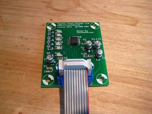
This is an advanced, surface mount board. It requires steady hands and patience to solder.
Don't worry though, You Can Do It!
The Magnetic Rotary Encoder board is based around the Austria Microsystems AS5040 chip. This chip allows you to sense the rotational position of a magnet. Sounds boring, right? Wrong! When you combine this chip with a motor, a motor driver, and an Arduino it allows you to create a servo motor of unlimited size and rotation. You can measure the rotation of the motor and control it so that it goes to the position you desire. Or, in the case of our extruder, you can measure the speed of the motor and have it rotate at exactly the speed you desire, regardless of the load on the motor.
- You'll need a soldering toolkit to do most of this.
- Read our Electronics Fabrication Guide if you're new.
Get It!
Full Kit
Raw Components
Files
<div class="thumb tright"></div>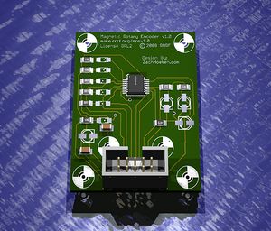
You can download the electronics files from Sourceforge.
This file contains the following:
- GERBER files for getting it manufactured
- PDF files of the schematic, copper layers, and silkscreen
- Eagle source files for modification
- 3D rendered image as well as POVRay scene file
- exerciser code to test your board.
Schematic

Interface
The AS5040 provides many different ways of getting the position data from the chip. Each one has its advantages and disadvantages, so feel free to use the one best suited to your needs.
Pinout
| Pin | Name | Function |
| 1 | PWM | A PWM output signal, where the width of the pulse (1 usec to 1023 usec wide) is based upon the position of magnet (0-360 degrees) |
| 2 | ANALOG | An analog output signal from 0-5v signifying the position of the magnet (0-360 degrees) |
| 3 | SELECT | The AS5040 provides a digital output using SSI, this is the select (or latch) pin. |
| 4 | CLOCK | The AS5040 provides a digital output using SSI, this is the clock pin. |
| 5 | DATA | The AS5040 provides a digital output using SSI, this is the data (or MISO) pin. |
| 6 | INDEX | When the magnet is at the 0 degrees position, this pin is HIGH, otherwise LOW. This pin will pulse once per revolution |
| 7 | B | The AS5040 outputs quadrature signals. This pin is the Quadrature Phase B signal |
| 8 | A | The AS5040 outputs quadrature signals. This pin is the Quadrature Phase A signal |
| 9 | GND | This is the ground pin. Connect this to ground on your Arduino. |
| 10 | 5V | This is the 5V input pin. Connect this to 5v on your Arduino. |
LEDS
| LED | Meaning |
| MAG+ | This is the Magnetic Field Increasing LED. If the magnetic field strength is increasing, this LED will light up. |
| MAG- | This is the Magnetic Field Decreasing LED. If the magnetic field strength is decreasing, this LED will light up. |
| QUAD_A | This LED is directly wired to Quadrature Phase A, it gives you a direct view of the chip activity. |
| QUAD_B | This LED is directly wired to Quadrature Phase B, it gives you a direct view of the chip activity. |
| INDEX | This LED is directly wired to the Index pin, it will flash once per revolution. |
| PWM | This LED is wired to the PWM pin, along with a capacitor. Its brightness will vary according to the position of the magnet. |
If both MAG+ and MAG- are on, it means your magnet is Out of Range. If they sporadically light during magnet rotation, it means your magnet alignment is slightly out of range. Adjust it accordingly until they do not light during normal use. Use these LEDs to align your magnet properly.
Build It
Board Bugs
- No bugs yet, please report any you find to the forums.
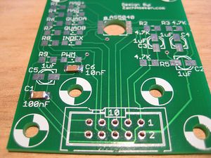
Printed Circuit Board
<div class="thumb tright"></div>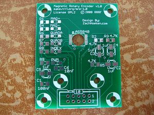
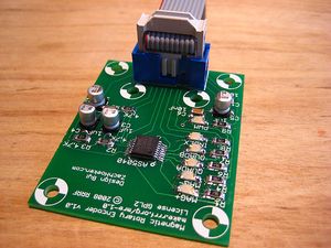
You can either buy this PCB from the RepRap Research Foundation, or you can make your own. The image above shows the professionally manufactured PCB ready for soldering.
Components
<div class="thumb tright"></div>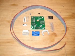
<iframe src="http://parts.reprap.org/embed/module/Magnetic+Rotary+Encoder+v1.0" width="600" height="500" frameborder="0">Visit http://parts.reprap.org/embed/module/Magnetic+Rotary+Encoder+v1.0</iframe>
Soldering Instructions
This is a mostly surface mount component board, so the techniques will be a bit different than usual. In addition to your standard soldering toolkit, you will also need the following:
- a soldering iron with a good, small tip
- some tweezers, or small needle nose pliers
- some thin solder (0.025" diameter or smaller)
- a flux pen, flux paste, or other flux dispensing device
- some solder wick
- a magnifying glass
Before you start, you may want to watch this video on Surface Mount Soldering and/or read the SparkFun tutorial.
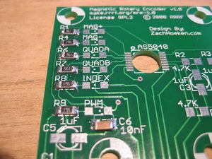
<div class="thumb tright"></div>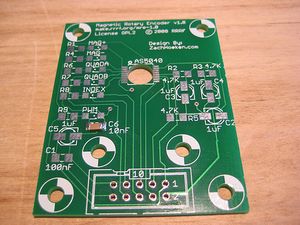
10nF capacitor
The 10nF and 100nF capacitors themselves are not marked, so we have marked the 10nF capacitor with blue marker. If you mix them up, don't worry its okay.
The orientation on this capacitor does not matter.
The basic process goes like this:
- apply a small bit of solder to one of the raw pads to prep it
- pick up component with tweezers, and apply a small amount of flux to the ends
- position the component in place and heat one side with the iron (causing it to bond to the pad on that side)
- solder the other side to the other pad. if its sticking up a bit, solder it until the entire chip heats up and settles in.
- you may need to add more solder to either side to get a nice solid joint
100nF capacitor
Follow the directions above to solder the non-marked capacitor in.
The orientation on this capacitor does not matter.
560 Ohm Resistors
These resistors will all be marked '561'. The orientation does not matter, but it helps to solder them so the text is all facing the same way. Do as I say, not as I do ;)
Solder them with the same technique you used for the capacitors.
4.7K Ohm Resistors
These resistors will be marked '472'. Solder them in just as with the 560 ohm resistors.
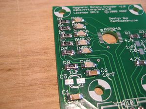
LEDS
The LEDs are polarized, meaning you need to solder them in the correct orientation! They will have green dots towards one side of the package. These dots need to match the dots on the silkscreen. Be careful, since the orientation changes for the various LEDs. Always check and double check the orientation before you solder.
Other than that, you can solder them using the same technique you used above. Be careful not to heat them up too much, as you may damage them.
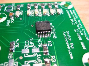
AS5040
This is the hardest part of the board. Take a quick break before you do it. Wipe the sweat from your brow, take a deep breath, and calm yourself.
1. 2. 3. 4. 5. Exhale.
Awesome, lets start. First off, the chip needs to be soldered in properly. There is a circle mark on the chip that corresponds to the mark on the silkscreen. Make sure they match up before you solder.
The basic soldering process goes like this:
- use flux on the legs of the chip and/or the board
- position the chip over the pads
- solder one corner of the chip to the corresponding pad
- solder the opposite corner of the chip to the corresponding pad
- solder the rest of the pins, ignoring solder bridges
- use the solder wick to remove any solder bridges
- profit!
If you're still confused, please watch this video. It will change your life. Maybe.
If all goes well, you'll have a nicely soldered chip. The rest is simple.
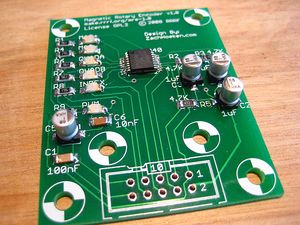
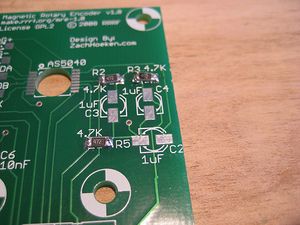
1uF Electrolytic Capacitors
These guys are the little tin-can looking things. They have polarity, so be sure to double check which way you are soldering them to the board. One side will have square corners, and the other will have beveled edges. Make sure you match these up with the silkscreen.
Once you understand how to place them, you'll want to prepare the surface for mounting just like you did with the other capacitors, resistors, and LEDs by applying a bit of solder to the empty pads. Then you simply solder the capacitor down one pad at a time. Yay!
IDC Header
This is where you will plug in the IDC cable to your board. Solder it so the center tab faces the center of the board. Just like it shows on the silkscreen!
This one is thru-hole and thus insanely easy compared to what you just did.
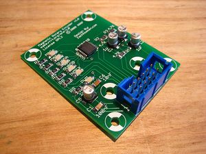
Insert IDC Connector
First, you must make an IDC cable. Next, insert it into the header. It is keyed, so it can only be inserted in one orientation. Yay!
Congratulations, you just soldered a fairly difficult board. Go have a frosty beverage of your choice to celebrate.
Mount It
GM3 Gear Motor
<div class="thumb tright"></div>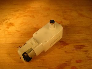
The Magnetic Rotary Encoder Board provides precise mounting holes to mount it to a GM3 Gearmotor. You'll need spacers that are 7/16" long to space the board far enough away.
Attach the Magnet
The first step is to mount the magnet on the GM3 gearmotor's non-output shaft. This is the shaft with one flat side, NOT the shaft with two flat sides. Get some super glue and put a dab on the shaft of the motor. Quickly place the magnet onto the shaft, being careful that the magnet is closely aligned with the motor shaft. It should be slightly inside the curve of the shaft. Press firmly for 10 seconds to allow the glue to bond. If you messed up, pry the magnet off and try again. It may take 2 applications of the superglue to get a good bond. Finally, clean off any gunk from the side and top of the magnet.
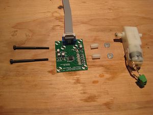
Mount the MRE Board
Using the M3 bolts, attach the MRE to the GM3 Motor using the spacers provided. The magnet should just barely enter the large drill hole beneath the chip. You can then mount the GM3 motor wherever you need it to be mounted. If you need more spacing, you can easily add a washer or two between the spacer and the motor.
More information on hacking the GM3 Gearmotor is here.
Other Uses
You can use the MRE board to measure rotation for many things, and we've provided 6 different mounting holes for you to use. The magnet can be positioned directly above or below the AS5040 chip, and we've provided a 6.1mm diameter hole that will help with aligning the magnet as well. Please refer to the AS5040 datasheet for more information on mounting tolerances.
Use It
Quadrature Output
[ ]
Quadrature Encoding is very useful. It allows you to determine both position and rotation direction in a simple manner. Not only that, but it is incremental, which means that you can use quadrature encoding to record positions that are as large as you can store in your variable!!!
Not only that, but it only uses 2 pins. Rad.
Here is an Arduino program to read the position via quadrature encoding. Connect the pins as follows:
| MRE Pin | Arduino Pin |
| 5V | 5V |
| GND | GND |
| QUAD_A | 2 |
| QUAD_B | 3 |
Then, upload this code, and open your Serial Monitor at speed 19200.
#define ENCODER_A_PIN 2 #define ENCODER_B_PIN 3 long position; void setup() { Serial.begin(19200); Serial.println("Started"); pinMode(ENCODER_A_PIN, INPUT); pinMode(ENCODER_B_PIN, INPUT); attachInterrupt(0, read_quadrature, CHANGE); } void loop() { Serial.print("Position: "); Serial.println(position, DEC); delay(1000); } void read_quadrature() { // found a low-to-high on channel A if (digitalRead(ENCODER_A_PIN) == HIGH) { // check channel B to see which way if (digitalRead(ENCODER_B_PIN) == LOW) position++; else position--; } // found a high-to-low on channel A else { // check channel B to see which way if (digitalRead(ENCODER_B_PIN) == LOW) position--; else position++; } }
Digital SSI Output
<div class="thumb tright"></div>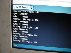
The AS5040 provides a digital output which is also very useful. It uses 3 pins, but provides some other useful features such as a checksum, and error flags to help you diagnose any potential errors. Additionally, it is possible to do some advanced things with the digital output, such as daisy chaining AS5040 chips to allow you to read multiple AS5040 chips with the same 3 pins, or allowing you to read them in parallel using 2 + N pins where N is the number of AS5040 chips to use.
It has some very useful potential.
Here is an Arduino program to read the position via the digital interface. Connect the pins as follows:
| MRE Pin | Arduino Pin |
| 5V | 5V |
| GND | GND |
| SELECT | 4 |
| CLOCK | 5 |
| DATA | 6 |
Then, upload this code, and open your Serial Monitor at speed 19200.
#define SELECT_PIN 4 #define CLOCK_PIN 5 #define DATA_PIN 6 void setup() { //setup our pins pinMode(DATA_PIN, INPUT); pinMode(CLOCK_PIN, OUTPUT); pinMode(SELECT_PIN, OUTPUT); //give some default values digitalWrite(CLOCK_PIN, HIGH); digitalWrite(SELECT_PIN, HIGH); Serial.begin(19200); } //variables to keep track of position int reading = 0; float angle = 0; void loop() { reading = readPosition(); if (reading >= 0) { angle = ((float)reading / 1024.0) * 360.0; Serial.print("Reading: "); Serial.print(reading, DEC); Serial.print(" Angle: "); Serial.println((int)angle, DEC); } else { Serial.print("Error: "); Serial.println(reading); } delay(1000); } //read the current angular position int readPosition() { unsigned int position = 0; //shift in our data digitalWrite(SELECT_PIN, LOW); delayMicroseconds(1); byte d1 = shiftIn(DATA_PIN, CLOCK_PIN); byte d2 = shiftIn(DATA_PIN, CLOCK_PIN); digitalWrite(SELECT_PIN, HIGH); //get our position variable position = d1; position = position << 8; {| border="1" |- position ||= d2; |} position = position >> 6; //check the offset compensation flag: 1 == started up if (!(d2 & B00100000)) position = -1; //check the cordic overflow flag: 1 = error if (d2 & B00010000) position = -2; //check the linearity alarm: 1 = error if (d2 & B00001000) position = -3; //check the magnet range: 11 = error if ((d2 & B00000110) == B00000110) position = -4; return position; } //read in a byte of data from the digital input of the board. byte shiftIn(byte data_pin, byte clock_pin) { byte data = 0; for (int i=7; i>=0; i--) { digitalWrite(clock_pin, LOW); delayMicroseconds(1); digitalWrite(clock_pin, HIGH); delayMicroseconds(1); byte bit = digitalRead(data_pin); {| border="1" |- data ||= (bit << i); |} } Serial.print("byte: "); Serial.println(data, BIN); return data; }
Analog Output
<div class="thumb tright"></div>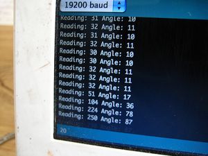
By using a filter circuit, the AS5040 is capable of outputting an analog position value. Its not nearly as accurate as the Quadrature or Digital outputs, but it is useful in its own right.
Here is an Arduino program to read the position via analog. Connect the pins as follows:
| MRE Pin | Arduino Pin |
| 5V | 5V |
| GND | GND |
| ANALOG | Analog 0 |
Then, upload this code, and open your Serial Monitor at speed 19200.
#define ANALOG_PIN 0 int reading = 0; float angle = 0; void setup() { Serial.begin(19200); Serial.println("Started"); } void loop() { reading = analogRead(ANALOG_PIN); angle = ((float)reading / 1024.0) * 360.0; Serial.print("Reading: "); Serial.print(reading, DEC); Serial.print(" Angle: "); Serial.println((int)angle, DEC); delay(1000); }
PWM Output
Coming soon. Anyone have a good idea on how to use this output?
Index Output
Coming soon. This one is pretty easy.
Index
other encoders
- the open-source OpenServo OpenEncoder seems surprisingly similar to this RepRap magnetic rotary encoder.