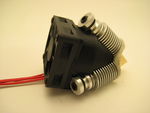
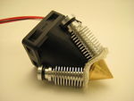
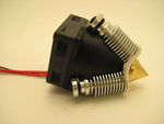
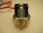
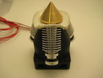
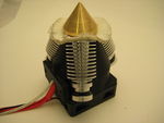
Diamond Hotend
Release status: working

| Description | triple filament hotend
|
| License | CC-BY-NC-SA
See License section below |
| Author | |
| Contributors | |
| Based-on | |
| Categories | |
| CAD Models | |
| External Link |

Click image for credits
Contents
- 1 Compact multicolor printhead
- 2 Features
- 3 Benefits of this design
- 4 Sources
- 5 Assembling
- 6 Firmware adaption
- 7 Slicer settings
- 8 Multi-material printing with Repetier Host
- 9 Developers
- 10 License
- 11 Revision History
- 12 Fun facts
- 13 How to get it
- 14 Adding An Extruder Motor To Ramps With CNC Shield
Compact multicolor printhead
Watch the video of our Prusa i3 Hephestos equipped with the Diamond Hotend printing 3D Hubs' mascot Marvin here
Features
- 3 pcs inputs for 1.7 mm filament
- Common 0.4 mm nozzle orifice
- Smallest possible mixing chamber for minimal waste and fast color change
- Cutout for standard 40W heater cartridge and leaded thermistor
- 3 pcs threaded mounting holes for state of the art E3D v6 HeatBreaks & HeatSinks
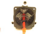
- Combined mounting bracket and airguide for optimal cooling by a 50mm high efficiency fan
- Optional pendant for attaching a 5015 blower fan for extrudate cooling
- Weight of assembled hotend: 250 grams (nozzle, HeatSinks, cooling shield, fan, heater cartridge & thermistor)
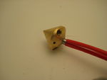
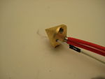
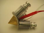
The key feature of The Diamond Hotend is the diamond shaped nozzle. We have designed the nozzle to have smallest possible mixing chamber, to make color shifts as fast as possible and to avoid unnecessary filament waste. To ensure rapid nozzle heat up we have constructed the nozzle as compact as possible.
Benefits of this design
- Easy calibration
- Better precision compared to multi-nozzle printing
- Prints with 3 different colors
- Minimal filament waste

Sources
These parts are recommended in order to construct a working Diamond hotend
Part list
- 1 x The Diamond Hotend nozzle File:Diamond Nozzle.pdf
- 3 x Thermal insulation sheet (made from lasercut fire blanket: diamond_thermal_insulation.dxf)
- 3 x E3D-Lite6 HeatSinks with bowden fittings
- 1 x Standard cartridge heater (12 Volt / 40 Watt / Ø:5.8 mm / L:20 mm)
- 1 x Leaded glass bead thermistor (EPCOS 100k NTC)
- 1 x Thermal compound
- 1 x Printed parts
- 1 x High efficiency fan 50 mm capable of delivering an airflow of at least 18 cubic feet per minute (e.g. Multicomp MC35357)
- 1 x Extension wire with 2P female Dupont for the 50 mm fan
- 1 x Heat shrink for the extension wire
- 4 x Zip ties (2.5x100 mm)
- 4 x M3 x 20 mm countersunk screw [1]
Accessories
- 3 x PTFE Bowden tube (DO:4 mm / DI:2 mm /L:500 mm)
- 3 x Bowden extruder
- 1 x Electronics capable of driving 6 stepper motors (eg. RUMBA)
- 1 x Radial blower fan 5015S is available from eBay in both a low and a high-power version (we found that the one with a label marked AV-5015S could deliver the most)
Assembling
Prusa i3 version
These instructions are written with Prusa i3 Hephestos in mind
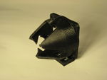
If you haven't already done so, or you want the one with the blower fan option, download and print out the Diamond Hotend Cooler Shield (http://www.thingiverse.com/thing:720520). For normal use we recommend printing the cooler shield in PLA. For printing with materials that require higher printing temperatures, we recommend printing the shield in ABS or another material with a higher glass transition temperature (Tg).
Insert the two M3 nuts into the hexagonal holes at the rear of the printed Cooler Shield and press them into place. If necessary use a soldering iron to heat the nuts and melt them into place.
The two holes are spaced 30.5 mm apart, hence it should fit most Prusa i3 printers, but check with your printer anyways - you may have to customize this part if your printer have different specifications.
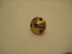
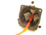
Apply a small amount of the thermal compound to the center hole of the Diamond Hotend.
Insert the heater cartridge into the center hole of the Diamond Hotend and press it in as much as possible. Wipe off excess compound. If there's no excess remove the heater cartridge and repeat from step 3.
Dip the thermistor tip into the remaining thermal compound and press it into the 2 mm hole in the Diamond Hotend along with some millimeters of the PTFE tubings, which will keep the thermistor locked in place.
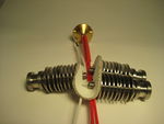
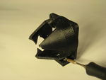
Stack the three Thermal Isolator Sheets, feed the wire ends through their corresponding holes, then firmly press the sheets onto the Heat Breaks of the HeatSinks.
Screw the HeatSinks loosely onto the Heat Breaks. Do not tighten yet, we will do this later.
Grap the wire ends from the heater cartridge along with the thermistor wire ends and feed them all the way through the pointy end of the Cooler Shield orienting the shield in such a way that the thermistor is located closest to the Cooler Shield mounting plate. Press the small black Bowden Fittings in place.
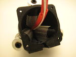
Making sure the wires remain in the central opening of the Cooler Shield, press the shield into the hotend assembly. The rear end of the HeatSinks must click equally into the grooves on the Cooler Shield. Retighten the HeatSinks but be careful not to over-tighten or the Heat Breaks might collapse.
Use 3 cable ties to attach the HeatSinks onto the Cooler Shield and the fourth cable tie to attach the wires onto the rear part of the Cooler Shield (the side which has a groove where the cables will fit).
Cut off any excess of the cable ties.
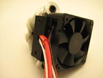
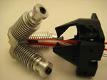
Mount the fan using 4 pcs M3 x 20 mm countersunk screws. Make sure to orient the fan such that the airflow goes down into the Cooler Shield (label side of fan pointing into the assembly) and the wires coming out at the same side as the other wires.
Attach the hotend mount onto the carriage using 2 pcs M3 x 20 mm along with 2 pcs M3 washers.
To avoid filament clogging and/or meltdown of the Cooler Shield the fan must be constantly running. Be sure to connect it directly to 12 volt by cutting the heat shrinking tube into two pieces, sliding them over each wire (black and red) and soldering the bare leads onto the included extension cord. On a RUMBA board there is a 2 pin terminal referred to as 12V. Connect the black wire to - and the red wire to +.
Strip the outer 5 mm of the heater cartridge wire ends and mount them in the Hotend power output screw terminal. On a RUMBA board this is done via the terminal referred to as HE0. The thermistor plug goes to the pins marked T0.
After heating up your Diamond Hotend the first time, you must carefully re-tighten the HeatSinks while hot. You may use a water pump size pliers but be extremely careful not to over-tighten. To avoid making marks or scratches on the HeatSinks you should put a piece of cloth in between.
Done!
Congratulations! You now have an assembled Diamond Hotend. You should now be ready for attaching 3 pcs 1.75 mm bowden extruders and the electronics.


Prusa i3 version with extrudate cooling
If you wish the benefits of actively cooling the extruded material while printing with your new Diamond Hotend (especially good for printing bridges and overhangs), we encourage you to browse to http://www.thingiverse.com/thing:720520. There you will find an alternate cooler shield file, this version features a pendant for attaching a 5015S radial blower fan.
- Download and print “diamond_cooler_shield_blower.stl”, and “bq_extruder_Tobera.stl”.
- Insert two M3 nuts into the cooler shield blower pendant.
- Screw the blower bracket in place using 2 pcs countersunk M3 x 10 mm screws.
- Screw the radial blower onto the blower bracket using 2 pcs M3 x 20 mm screws.
- Screw the blower nozzle onto the blower bracket using 1 pcs M3 x 15 mm screw.
- Extend the wires from the blower
Firmware adaption
For the development of this hotend we have been using the RUMBA motherboard running Marlin
The necessary firmware adaptions listed below are centered on Marlin by Erik Zalm
In Configuration.h
#define MOTHERBOARD 80
#define EXTRUDERS 3
#define TEMP_SENSOR_0 6
#define TEMP_SENSOR_1 6
#define TEMP_SENSOR_2 6
In Pins.h (scroll down into the “RUMBA pin assignment” section)
#define TEMP_0_PIN 15
#define TEMP_1_PIN 15
#define TEMP_2_PIN 15
Rumba setup
If you are using a RUMBA motherboard (not included) to control your printer, here is how to set it up for the Diamond Hotend:
- Install the RUMBA TAURINO driver from http://reprap.org/wiki/RUMBA (scroll down to the RUMBA_USB_Driver_for_Windows section)
- Move the on-board jumper from Stand-alone to USB Power [2].
- Attach a MINI-USB cable.
- If you do not already have Arduino IDE installed on your computer, download and install it from http://arduino.cc/en/Main/Software. For general info on how to upload firmware onto the motherboard please see http://arduino.cc/en/Guide/HomePage.
- Using Arduino IDE, upload the Marlin (Stable) firmware to the motherboard. If you are using a different printer you might need to edit the firmware on beforehand.
- Move back the jumper to the Stand-alone position.
- Mount stepsticks into the sockets X, Y, Z E0, E1 and E2 on the Rumba motherboard. Caution: be sure to orientate them such that the corner pin marked EN is closer to the motor output terminals.
- Attach the thermistor to the T0 pin header.
- Power supply wires (12 volt) mounts in the MAIN-PWR screw terminal.
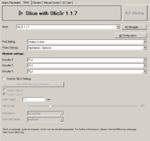
Slicer settings
Slic3r
Print Settings tab:
Layers and perimeters → Layer height: 0.2 mm
Printer Settings tab:
General → Capabilities → Extruders: 3
Custom G-code → Start G-code:
T0
M190 S[first_layer_bed_temperature]
M109 S[first_layer_temperature]
G28
G0 Z5
G0 X0 Y0
G91
T0
G0 E5 F100
T1
G0 E5 F100
T2
G0 E5 F100
T0
G90
G0 X20 Z0 F1000
G0 Z0.1
G92 E0
Custom G-code → End G-code
T0
M104 S0
M140 S0
G28 X0
G91
G1 Z10 F1200
M84
Extruder 1 → Size → Nozzle diameter: 0.4 mm
Extruder 1 → Position → Extruder offset: X: 0 mm
Extruder 1 → Position → Extruder offset: Y: 0 mm
Extruder 1 → Retraction → Length: 7 mm
Extruder 1 → Retraction → Lift Z: 0.1 mm
Extruder 1 → Retraction → Speed: 100 mm/s
Extruder 1 → Retraction → Extra length on restart: 0 mm
Extruder 1 → Retraction when tool is disabled → Length: 7 mm
Extruder 1 → Retraction when tool is disabled → Extra length on restart: 0.2 mm
(The same settings apply to extruder 2 & 3)
Cura
At the time of writing, triple-material slicing with Cura is not recommended. We tried, but the current version (v.15.01 at the time of writing) of Cura only works for dual material printing. However the developers of Cura has mentioned that this will become a feature from the next major version change.
Other slicing software
If you prefer using slicing software that has not been mentioned here and you have successfully applied workable settings, we encourage you to share these settings with the rest of the community by uploading them to one of the free online file sharing sites. Be sure to use the name Diamond Hotend either in the title, description or tags and add it to this section.
Multi-material printing with Repetier Host
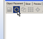
Add your desired multi-material object (.amf file) using the encircled plus symbol on the right pane.
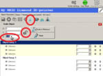
Again using the encircled plus symbol add “primetower.amf” then click the encircled areas and enter a Z-value to scale it in the Z-direction equal to the object in step 1.
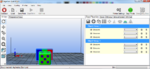
Verify that the primetower is located behind the object to be printed as seen from View → Front View.
Choose Slic3r settings appropriate for the object you want to print and press “Slice with Slic3r...”.
You can now print directly from Reptier Host or choose to save on the SD-card.


![[2]](http://reprap.org/wiki/File:Diamond_Hotend_Rumba_cut_PwrSelect.jpg)
The primetower.amf file is accessible for download via the link mentioned in step 1 of the assembling instructions.
For further info on using Repetier Host please refer to the Repetier-Host Documentation: http://www.repetier.com/documentation/repetier-host/
Developers
The source code for the cooling shield is an OpenSCAD script that you can download here: thingiverse thing 720520
If you are making a Diamond Hotend mounting bracket for a different printer we encourage you to share your design with the rest of the community by uploading it to one of the free online file sharing sites. Please use the name Diamond Hotend either in the title, description or tags and add a link on this page.
License
The Diamond Nozzle is released under the Creative Commons CC-BY-NC-SA license. We chose this license because of the significant amount of man-hours invested in the project. The cooling shield and related parts that we have developed are released under the CC-BY-SA license. We intent to release the original project as a whole under the CC-BY-SA license, if and when we decide to publish a new or superior version of the project.
Revision History
Production batches:
Rev. 0.1a (2 pcs produced for proof of concept)
Rev. 0.2b (10 pcs produced for beta testing)
Rev. 1.0 (Pending for successful Kickstarter campaign)
Fun facts
Beginning April 1st. a Kickstarter campaign were launched to initiate the production. A big thank you to everyone goes out to every one of the backers supporting this project by pedging in on the campaign. As of April 3rd. the campaign had reached its goal with still 27 days to go. At the end of the campaign the goal was met by over 400% of the original sum pledged (DKK150000).
How to get it
After delivery to the people who pledged in during the Kickstarter period we expect to offer the hotend from our homepage. This is estimated to take place during the summer of 2015.
Adding An Extruder Motor To Ramps With CNC Shield
This outlines the hardware connections required to add an extruder to your existing RAMPS board for cheap.
Parts needed (Can All Be Bought from China for Under $10 Shipped to the US):
- 1 x CNC Shield v3. Can Be had for $3.70 from China
- 4 x 10cm Female to Female Jumper Wires
- 1 x 20cm Female to Female Jumper Wires (You can use all 5 20cm if you want.)
- 1 x Stepper Motor Driver DRV8825 Or A4988 (China Clones Can be Had for Under $1.70 for DRV8825
- 5 x Standard Header Jumpers
- 2 x Short Scrap Stranded Wire 18 AWG or Larger.
- 2 x M3 Screws 8-16mm Length
- 4 x M3 Nuts
- 1x Printed RAMPS Bracket [3]
Steps:
- Start by printing the bracket
- Attach the bracket to the CNC board with the M3 Screws. (Use the nuts as spacers)
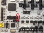
- Install the 5 Jumpers as shown here.

- Find The Enable pin on your stepper Driver

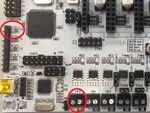
- Make Sure the Enable Pin on your driver lines up with the enable pin on the CNC Shield then install it into the shield on the A Axis (Typically the Red Colored Headers)

- Examine the pin locations here and make the following connections: [[4]]
![[4]](http://reprap.org/mediawiki/images/archive/c/ca/20131210184132!Arduinomega1-4connectors.png)
* AUX-1
* 5v to 5v on CNC Board
* GND to GND on CNC Board
* D1 to A.Step on CNC Board
* D0 to A.Step Direction on CNC Board
* AUX-2
* D66 to Enable on CNC Board Using 20cm Wire
- Final Connections Should look something like this:

- Hook Up to 12v or 24v supply on the CNC Board. (It does not need to be the same supply as the rest of the RAMPS Board ex. if you do not have enough current from 1 power supply.)
This method can be used to add up to 4 extra motors while still leaving 4 IO pins, fan extender, and LCD functional. There is no need to go buy an expensive board meant for a kraken because we only use 1 heater.
This method can also be used for other boards like (Melzi, Ultimaker, Printrboard, etc.)
Firmware Changes
Note: This will only work if being done for a RAMPS 1.3 or 1.4 Board. In configuration.h change the lines to the following:
- define EXTRUDERS 3
- define TEMP_SENSOR_0 6
- define TEMP_SENSOR_1 6
- define TEMP_SENSOR_2 6
Ensure it is setup so the power outputs are for only 1 extruder. i.e, one of the following:
- define MOTHERBOARD BOARD_RAMPS_13_EFB
- define MOTHERBOARD 33
- define MOTHERBOARD BOARD_RAMPS_13_EFF
- define MOTHERBOARD 35
The top 2 are equivalent and have the power outputs for an extruder, fan and bed (EFB), the bottom 2 are equivalent and have power outputs for an extruder and 2 fans (EFF).
And in pins.h: You may need to add:
- define E2_MS1_PIN -1
- define E2_MS2_PIN -1
In the RAMPS section (under where it has "if IS_RAMPS", after the else for if MB(3DRAG), if it has #define SDPOWER right after it is the wrong one) you need to add:
   #define E2_STEP_PIN        0
   #define E2_DIR_PIN         1
   #define E2_ENABLE_PIN      66
If you chose EFF, then change:
 #if MB(RAMPS_13_EFB) || MB(AZTEEG_X3)
   #define HEATER_1_PIN       -1
 #else
   #define HEATER_1_PIN       9    // EXTRUDER 2 (FAN On Sprinter)
 #endif
To
 #if MB(RAMPS_13_EFB) || MB(AZTEEG_X3)
   #define HEATER_1_PIN       -1
 #else
   #define HEATER_1_PIN       -1    // EXTRUDER 2 (FAN On Sprinter)
 #endif
And change the following (near line 700):
- define TEMP_1_PIN 13
And shortly below, after the else:
- define TEMP_2_PIN 13