RUMBA
|
English • العربية • български • català • čeština • Deutsch • Ελληνικά • español • فارسی • français • hrvatski • magyar • italiano • română • 日本語 • 한국어 • lietuvių • Nederlands • norsk • polski • português • русский • Türkçe • українська • 中文(中国大陆) • 中文(台灣) • עברית • azərbaycanca • |
Release status: Working

| Description | R.eprap U.niversal M.ega B.oard with A.llegro driver
|
| License | |
| Author | |
| Contributors | |
| Based-on | |
| Categories | |
| CAD Models | Altium
|
| External Link |
Contents
- 1 Summary
- 2 Safety Tip
- 3 RUMBA USB Driver for Windows
- 4 Features
- 5 Motor Driver
- 6 Motors
- 7 Endstops
- 8 Thermistors
- 9 Smart Controller (optional)
- 10 USB
- 11 RUMBA Wiring
- 12 RUMBA Firmware Pin Configuration
- 13 JTAG & ISP (for firmware developer)
- 14 Open Source Files
- 15 Where to get it?
- 16 Troubleshooting
Summary
RUMBA (R.eprap U.niversal M.ega B.oard with A.llegro driver) RUMBA is a feature rich all-in-one electronics solution for Reprap and other CNC devices.
It features an onboard ATmega2560. Its six motor outputs are powered by Pololu pin compatible stepper drivers.
The board features a developer friendly expansion port supporting giving access to all unused I/O, ADC and I2C pins.
RUMBA is designed to be flexible in the user's power source availability, allowing any power supply from 12V-35V.
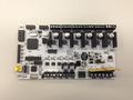
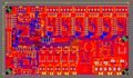
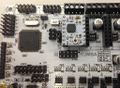
RUMBA board
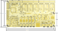
RUMBA PCB rendering
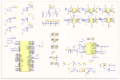
RUMBA schematic
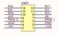
RUMBA schematic EXP3 connector
RUMBA PCB all layer


Safety Tip
Once you start putting electricity into your RepRap - even at just 12 volts - you have to take basic, common sense precautions to avoid fires.
Just in case these fail, test your workshop smoke detector.
Got no smoke detector? Get one!
RUMBA USB Driver for Windows
- NEW : Easy driver setup for Windows 8/7/Vista/XP 32 and 64 bit
 File:RRD RUMBA TAURINO DriverSetup.zip
- CLASSIC: (can cause problems with Windows 8 and Vista/7 64bit, use the easy method from above instead)
When you attach RUMBA for the first time to a Windows computer you might need to provide a driver (INF file). File:RRD-RUMBA USB DRIVER.zip
Features
- compact size: 135mm x 75mm
- fully integrated all in one solution:
- Arduino 2560-R3 compatible (works with Sprinter, Repetier, Marlin out of the box)
- ATmega16U2 (with enhanced firmware) for high speed USB serial connection (up to 2MBit)
- UNIVERSAL POWER:
- can be used with 12V-35V for motors / heated bed
- integrated high precision power regulators (DC/DC) for:
- 12V (FAN/Light/...) and
- 5V (ATmega2560/Logic)
- power input selector for ATmega/logic (stand alone or power from USB)
- easy DISPLAY + SD-CARD connector:
- RepRapDiscount SmartController compatible pin header on board
- up to 6 motor driver with easy micro stepping setup (micro switches) which can be used for:
- TRIPLE extruder
- DUAL Z driver and DUAL extruder
- ...
- 5x temperature ADC connectors for thermistors:
- e.g. 3x extruder thermistor + 1x heated bed thermistor + 1x chamber thermistor
- 5x PWM capable power mosfet outputs (3 with voltage selector for MainPower/12V):
- e.g. 3x (MainPower) extruder heater cartridge/power resistor + 1x (12V) fan + 1x (12V) light
- 1x PWM capable power mosfet with extended cooling area for heated bed
- 6x end stop connectors with power supply
- Xmin/Xmax/Ymin/Ymax/Zmin/Zmax
- can be used for mechanical, opto, hall, ... end stops
- screw terminals *and* pin header for easy motor connection:
- can be used with existing 4 pin Molex plug on motor cable
- easy to attach cables without plug
- USB connector and USB pin header (useful when mounting in a small box)
- Power and ALL unused pins available on EXP-3 feature connector:
- +5V and +12V
- 2x ADC
- 2x PWM I/O
- 4x I/O
- I2C
- full JTAG support
- JTAG can be used during full operation (no shared pins)
- easy to develop/debug new or optimized firmware using Atmel Studio
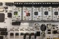
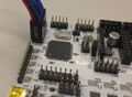
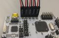
Motor Driver
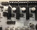
Stepper switches
Stepper driver attached
Stepper drivers ok/wrong
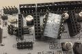
Stepper driver back


Microstepping
Some versions of the Rumba contain dip switches located underneath the driver boards, but current versions may contain a row of 3 jumpers.
with DRV8825
| 1 | 2 | 3 | step mode |
|---|---|---|---|
| 0 | 0 | 0 | Full step (2-phase excitation) with 71% current |
| 1 | 0 | 0 | 1/2 step (1-2 phase excitation) |
| 0 | 1 | 0 | 1/4 step (W1-2 phase excitation) |
| 1 | 1 | 0 | 8 microsteps / step |
| 0 | 0 | 1 | 16 microsteps / step |
| 1 | 0 | 1 | 32 microsteps / step |
| 0 | 1 | 1 | 32 microsteps / step |
| 1 | 1 | 1 | 32 microsteps / step |
sources:
from the ic manual. http://www.pololu.com/file/download/drv8825.pdf?file_id=0J590
http://forum.reprapdiscount.com/threads/manual.613/
http://forum.reprapdiscount.com/threads/micro-stepping.614/
with A4988
MS1 MS2 MS3 Microstep
Low Low Low 1
High Low Low 1/2
Low High Low 1/4
High High Low 1/8
High High High 1/16
Sources:
pololu.com/product/1182
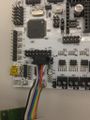
Motors
Motor on pin header
Motor on screw terminal


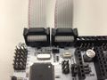
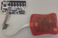
Endstops
Endstop cable
Multiple endstop cable


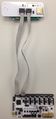
Thermistors
Thermistor cable

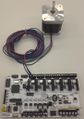
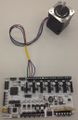
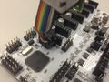
Smart Controller (optional)
Rumba board and SmartController
SmartController cable


USB
The Rumba uses a standard USB Mini-b (5-pin) female connector.
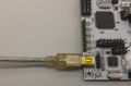
USB cable

Wiring for the 4-Pin USB Connector:
Starting from the black triangle the pins-outs are:
mass data+ data- vcc
|>______[]________[]________[]________[]
black green white red
RUMBA Wiring
Wiring plan based on available information , may contain wrong information ! / recheck necessary.

ATX power supply (controlled with RUMBA)

Set the power jumper in "stand alone" position
Connect GND from your ATX power supply to USB header Pin1 (where the black triangle is)
Connect 5 VSB from your ATX power supply (+5 VDC Standby Voltage) to USB header Pin4
Connect GND and PS ON (Power Supply On) from your ATX power supply to PS ON header, polarity doesn't matter
You'r now able to switch your power supply on and off via gcode or smart controler. With ATX +5 VDC Standby Voltage RUMBA is always powered on even if the power supply is turned of via RUMBA.
FAN0
Can be activated with the usual M106 Sxxx and deactivated with M107 (or M106 S0)
FAN1
Could be activated by using Mcode : M42 P8 Sxxx (0 < xxx < 255)
RUMBA Firmware Pin Configuration
This is an example only! Most likely your firmware of choice will have support for RUMBA built in
As of Marlin v1.0.0 pins.h contains the below suggested definitions, you should only need to change Configuration.h.
To flash your firmware of choice with the Arduino suite you have to select "Arduino Mega 2560 or Mega ADK" as Board.
Add to pins.h:
/****************************************************************************************
* RUMBA pin assignment
*
****************************************************************************************/
#if MOTHERBOARD == 80
#define KNOWN_BOARD 1

#ifndef __AVR_ATmega2560__
 #error Oops!  Make sure you have 'Arduino Mega' selected from the 'Tools -> Boards' menu.
#endif

#define X_STEP_PIN         17
#define X_DIR_PIN          16
#define X_ENABLE_PIN       48
#define X_MIN_PIN          37
#define X_MAX_PIN          36

#define Y_STEP_PIN         54
#define Y_DIR_PIN          47
#define Y_ENABLE_PIN       55
#define Y_MIN_PIN          35
#define Y_MAX_PIN          34

#define Z_STEP_PIN         57
#define Z_DIR_PIN          56
#define Z_ENABLE_PIN       62
#define Z_MIN_PIN          33
#define Z_MAX_PIN          32

//to use Z_DUAL_STEPPER_DRIVER in Marlin
#define Z2_STEP_PIN        26
#define Z2_DIR_PIN         25
#define Z2_ENABLE_PIN      27

#define E0_STEP_PIN        23
#define E0_DIR_PIN         22
#define E0_ENABLE_PIN      24

#define E1_STEP_PIN        26
#define E1_DIR_PIN         25
#define E1_ENABLE_PIN      27

#define E2_STEP_PIN        29
#define E2_DIR_PIN         28
#define E2_ENABLE_PIN      39

#define LED_PIN            13

#define FAN_PIN            7
//additional FAN1 PIN (e.g. useful for electronics fan or light on/off) on PIN 8

#define PS_ON_PIN          45
#define KILL_PIN           46

#define HEATER_0_PIN       2    // EXTRUDER 1
#define HEATER_1_PIN       3    // EXTRUDER 2
#define HEATER_2_PIN       6    // EXTRUDER 3
//optional FAN1 can be used as 4th heater output: #define HEATER_3_PIN       8    // EXTRUDER 4
#define HEATER_BED_PIN     9    // BED

#define TEMP_0_PIN         15   // ANALOG NUMBERING
#define TEMP_1_PIN         14   // ANALOG NUMBERING
#define TEMP_2_PIN         13   // ANALOG NUMBERING
//optional for extruder 4 or chamber: #define TEMP_2_PIN         12   // ANALOG NUMBERING
#define TEMP_BED_PIN       11   // ANALOG NUMBERING

#define SDPOWER            -1
#define SDSS               53
#define SDCARDDETECT       49
#define BEEPER             44
#define LCD_PINS_RS        19
#define LCD_PINS_ENABLE    42
#define LCD_PINS_D4        18
#define LCD_PINS_D5        38
#define LCD_PINS_D6        41
#define LCD_PINS_D7        40
#define BTN_EN1            11
#define BTN_EN2            12
#define BTN_ENC            43
//encoder rotation values
#define BLEN_C 2
#define BLEN_B 1
#define BLEN_A 0
#define encrot0 0
#define encrot1 2
#define encrot2 3
#define encrot3 1

#endif //MOTHERBOARD==80
Change in Configuration.h:
#define MOTHERBOARD 80
if you are connecting the Reprap discount smart controller uncomment this line:
#define REPRAP_DISCOUNT_SMART_CONTROLLER
JTAG & ISP (for firmware developer)
JTAG
ISP ATmega2560
ISP 16U2 (USB to Serial)


ATmega 2560 STK500v2/Arduino2560 Bootloader
HEX: File:RRD-RUMBA ATmega2560 ArduinoBoot.hex.zip
FUSES: E: 0xFD / H: 0x10 / L: 0xFF
- BOD=2.7V
- OCD+JTAG+ISP=ENABLED
- EESAVE=ENABLED
- BOOTSZ=4k
- BOOTRST=ENABLED
- EXTXOSC_8MHZ_XX_16KCK_65MS
Source: Arduino bootloader
16U2 LUFA/Arduino based USB2Serial Firmware
HEX: File:RRD-RUMBA ATmega16U2 USB2Serial.hex.zip
FUSES: E: 0xF6 / H: 0xD9 / L: 0xFF
- BOD=2.7V
- ISP=ENABLED
- EXTXOSC_8MHZ_XX_16KCK_65MS
Source: File:RRD-RUMBA SRC 16U2 FIRMWARE.zip (Atmel Studio 6 project)
Open Source Files
You can find the open source files here: http://forum.reprapdiscount.com/forums/oss/
Where to get it?
- Worldwide: RepRapDiscount online shop
- Worldwide: Geeetech
- France: eMotion Tech
- Germany: reprapteile.de
- Australia: Robotronics
Troubleshooting
USB connection (Writing in progress)
Symptoms
without any reason, the USB connection to the RUMBA is not possible. When connecting the USB cable to the computer, the operating system does not see any device. If the board is provided with a SD card reader, printing with a SD card is still possible.
Correction
First, be sure that the problem is not due to a bad position of the power jumper. The problem could be caused by the USB2Serial firmware. Then, you should flash the firmware following these steps:
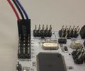
- Set the power jumper in "USB powered" position.
- Place a jumper slightly on the two pins pointed by the white arrow (see picture below)
- If the board is not mounted on your printer, place it on a clean, dry and insulated surface.
- Connect the USB cable on the board, and connect it on your computer
- Remove the jumper (be careful not to make short-circuit, do not use metallic tools). The TX and RX leds are flashing: the board is now in DFU mode.

If you are running Linux, you can now flash the firmware by doing this:
- Download and unzip File:RRD-RUMBA ATmega16U2 USB2Serial.hex.zip on your home folder.
- Install the software dfu-programmer. You must have the version 0.5.5 or above (Ubuntu 13.10 or higher).
- With root privileges (or sudo command), execute this command line to flash the firmware:
sudo dfu-programmer atmega16u2 flash RRD-RUMBA_ATmega16U2_USB2Serial.hex
- You can now disconnect and reconnect the USB cable, and try to connect your host software to the board. The board should now be listed with the "lsusb" command.
RepRapDiscount Smart Controler
Symptoms
The smart controler is beeping and flashing, rumba isn't responding
Correction
On some rumba boards the silk screen labeling on EXP1 and EXP2 is wrong. Try turning each connector by 180°.