Ohm/How to build an OHM
This page is a development stub. Please enhance this page by adding information, cad files, nice big images, and well structured data!
Contents
- 1 Introduction
- 2 Mechanical Construction
- 3 Electrical Construction
Introduction
The Open Hybrid Mendel (OHM) has several advantages over the generic Mendel model. Mainly, it is more flexible. The extruder carriage and printing board are designed to easily pop off the machine without unscrewing any parts.
All STL files mentioned in this article are referring to, and can be downloaded from the OHM Parts section.
Mechanical Construction
Frame
Frame Triangles
Parts
Total # of assemblies: 2
| Name | Qty/assembly | Total Qty | Type |
| Camiel_frame_vertex_6off | 3 | 6 | RP |
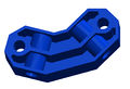
| prusa_bar-clamp_2off | 2 | 4 | RP |
| m8-nut | 14 | 28 | Fastener |
| m8-washer | 14 | 28 | Fastener |
| m8-threaded rod D | 3 | 6 | Threaded Rod |
Reprapped parts
Camiel_frame_vertex_6off
prusa_bar-clamp_2off


Assembly
(Assembly guide. Delete this note when section is finished)
Tips
When you assemble the frame triangles, it will be easier if you assemble the two top vertices the last. To insert the rod into the vertices, you can tie two nuts tight together and then use a wrench to screw in the rod.
Connecting the Triangles
Parts
Total # of assemblies: 1
| Name | Qty/assembly | Total Qty | Type |
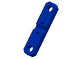
| y-motor-bracket_1off_mod3-15 | 1 | 1 | RP |
| y-idler-bracket_1off | 1 | 1 | RP |
| m8-nut | 44 | 44 | Fastener |
| m8-washer | 44 | 44 | Fastener |
| m8-threaded rod E | 4 | 4 | Threaded Rod |
| m8-threaded rod F | 3 | 3 | Threaded Rod |
Reprapped parts
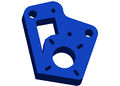
y-motor-bracket_1off_mod3-15
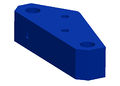
y-idler-bracket_1off


Assembly
(Assembly guide. Delete this note when section is finished)
Tips
It is easier to assemble the triangles, if connected both ends first, and then connect the bottom two rods.(Extra tips to help assemble. Delete this note when section is finished)
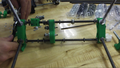
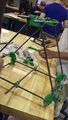
View of unfinished Y-axis
View of unfinished Y-axis
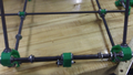
Finished Frame


Z Drive System
Z-Axis Motor Mounts & Drive Rods
Parts
Total # of assemblies: 2
| Name | Qty/assembly | Total Qty | Type |
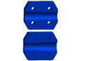
| z-prusa-motor-mount_2off | 1 | 2 | RP |
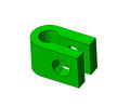
| z-bar-top-clamp_2off | 1 | 2 | RP |
| m3x20-cap | 4 | 8 | Fastener |
| m3-washer | 4 | 8 | Fastener |
| m8-nut | 2 | 4 | Fastener |
| m8-washer | 4 | 8 | Fastener |
Reprapped parts
z-prusa-motor-mount_2off
z-bar-top-clamp_2off


Assembly
Leave the smooth rod clamps loose and save the threaded rod for "connecting the x and z axis" section, since the x assembly needs to slide on before these are attached. (Assembly guide. Delete this note when section is finished)
Tips
(Extra tips to help assemble. Delete this note when section is finished)
Assembly of Z-axis can be started from sticking everything together in one rod. Settling all the parts (including the two top vertices for the frame triangle) on Z axis and connecting them with rod at one side, then insert the rod for the other side.
X-Z Assembly
X-Axis Motor Mounts
Parts
(Parts needed for assembly. Delete this note when section is finished)
Assembly
(Assembly guide. Delete this note when section is finished)
Tips
(Extra tips to help assemble. Delete this note when section is finished)
X-Axis Vertical Bearing
See Mendel X-Axis for further information.
Parts
Total # of assemblies: 2
| Name | Qty/assembly | Total Qty | Type |
| x-axis-side-plate-nut-jig_2off | 1 | 2 | RP |
| x-bar-clamp-m4_4off | 2 | 4 | RP |
| x-vert-drive-nut-trap_4off | 2 | 4 | RP |
| x-vert-drive-side-plate-180-end_2off | 2 | 4 | RP |
| m4-nut | 4 | 8 | Fastener |
| m4-nylock | 4 | 8 | Fastener |
| m4-washer | 16 | 32 | Fastener |
| m4x40-cap | 8 | 16 | Fastener |
| m8-nut | 1 | 2 | Fastener |
Reprapped parts

Assembly

First, assemble the x-vert-drive-nut-trap_4off. To do this, you need a lighter, four m4 nuts and a m4x40-cap. Place an m4 Nut on the end of the m4x40-cap and heat with the lighter. Caution: Do not heat for too long or the m4x40-cap will become very hot.

Push the heated nut into one of the hexagonal holes in the x-vert-drive-nut-trap_4off. Repeat for all four nuts.

Screw x-vert-drive-side-plate-180-end_2off and x-bar-clamp-m4_4offtogether using m4x40-cap and washers. Do not screw them all the way in.

Screw x-vert-drive-nut-trap_4off into x-vert-drive-side-plate-180-end_2off using a diagonal pattern. Remember to use washers. Do not screw them all the way in.


Repeat previous steps to create other half. Make sure that you place the screws diagonally in a way that they do not interact with the other screws.

Place the x-vert-drive-nut-trap_4off in between the bottom half of the two sides and line up screws. Screw in the M4 screws until they sit in the nuts and are firmly in place. This could take some adjustment.
Place an M8 nut in between the two trap sides. Then screw the upper screw together. Tighten all screws in steps.


Tips
- In some cases, though it is not necessary, it may help if you drill out the holes before assembling.
- To help align the screw holes, place on screw in, clamp the parts, and drill the rest of the holes.
Assembling the X-Axis
Parts
(Parts needed for assembly. Delete this note when section is finished)
Assembly
(Assembly guide. Delete this note when section is finished)
Tips
(Extra tips to help assemble. Delete this note when section is finished)
Connecting the X-Axis to the Z-Axis
Parts
Total # of assemblies: 2
| Name | Qty/assembly | Total Qty | Type |
| pla_coupling_nophead-1piece_4off | 2 | 4 | RP |
| m3x25-cap | 4 | 8 | Fastener |
| m3-nylock | 4 | 8 | Fastener |
| m3-washer | 8 | 16 | Fastener |
| m8-threaded rod G | 1 | 2 | Threaded Rod |
| m8-smooth rod B | 1 | 2 | Smooth Rod |
Reprapped parts
pla_coupling_nophead-1piece_4off

Assembly
(Assembly guide. Delete this note when section is finished)
Tips
(Extra tips to help assemble. Delete this note when section is finished)
Z and X axes Endstops
Parts
(Parts needed for assembly. Delete this note when section is finished)
Assembly
(Assembly guide. Delete this note when section is finished)
Tips
(Extra tips to help assemble. Delete this note when section is finished)
OpenY Axis
Y-axis Guide Bars
Parts
(Parts needed for assembly. Delete this note when section is finished)
Assembly
(Assembly guide. Delete this note when section is finished)
Tips
(Extra tips to help assemble. Delete this note when section is finished)
OpenY Assembly
Parts
(Parts needed for assembly. Delete this note when section is finished)
Assembly
(Assembly guide. Delete this note when section is finished)
Tips
(Extra tips to help assemble. Delete this note when section is finished)
Print Bed
Parts
(Parts needed for assembly. Delete this note when section is finished)
Assembly
(Assembly guide. Delete this note when section is finished)
Tips
(Extra tips to help assemble. Delete this note when section is finished)
Motors, Belts and Endstops
Parts
(Parts needed for assembly. Delete this note when section is finished)
Assembly
(Assembly guide. Delete this note when section is finished)
Tips
(Extra tips to help assemble. Delete this note when section is finished)
Extruder
Carriage
Parts
(Parts needed for assembly. Delete this note when section is finished)
Assembly
(Assembly guide. Delete this note when section is finished)
Tips
(Extra tips to help assemble. Delete this note when section is finished)
Motor Mount
Parts
(Parts needed for assembly. Delete this note when section is finished)
Assembly
(Assembly guide. Delete this note when section is finished) This unfinished part includes the main driven gear, idler and lastly the main section.
Extruder part work in progress

Tips
(Extra tips to help assemble. Delete this note when section is finished)
Hot Tip + Electronics
Parts
(Parts needed for assembly. Delete this note when section is finished)
Assembly
(Assembly guide. Delete this note when section is finished)
Tips
When you feel like the tip is stuck, heat it up, and then use another piece of filament to quickly suck out the part that were stuck in the tip. (Extra tips to help assemble. Delete this note when section is finished)
Spool
Spool Assembly
Parts
(Parts needed for assembly. Delete this note when section is finished)
Assembly
(Assembly guide. Delete this note when section is finished)
Tips
(Extra tips to help assemble. Delete this note when section is finished)
Spool Mount
Parts
(Parts needed for assembly. Delete this note when section is finished)
Assembly
(Assembly guide. Delete this note when section is finished)
Tips
(Extra tips to help assemble. Delete this note when section is finished)
Electrical Construction
RAMPS
Motherboard
RAMPS 1.4 is used as our mother board.


Soldering Tip
It is better to solder from the center of the mother board to the edge. If you solder the pins on the edge first, they will make it difficult to solder the pins in the center.

When solder the larger pins, do not over heat them, and also plug them into another board before soldering.
Top pins
Solder 1 1x6, 6 1x4, and 7 2x3 pin headers on top of the board. The long post should be standing up to take a connector.
Solder one leg on each one to tack them into place. Then re-heat the joint and push on the component until it is perfectly situated.
Then you'll want to solder the rest of the leads. You will get burnt if you touch the other side of the pin you are soldering.

Driver sockets
Place the female headers for the stepper drivers on top of the board.
You can use the 1x8 and 1x6 pin headers to jig them straight. Turn the board over and solder these pins.

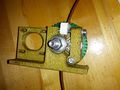
D1, D2 - Diodes
These must be placed in the proper orientation. The band on the diode must be turned the same way as the mark on the board.
Definitely solder D2 in. D2, F1, and F2 are shown installed here.
D1 should only be installed if the 5A rail is powered by 12V. It can be omitted and the Arduino will be powered from USB.
You will want D1 installed if you add components to print without a PC.
To reiterate, D1 MUST be omitted if you are powering the 5A rail by more than 12V, or the power is not absolutely clean, otherwise you may damage your ramps.

F1 - MFR500 Fuse
This is the smaller yellow fuse. This can be placed in any orientation.
When soldering the fuses it is best to use a piece of 3mm filament or something similar to keep the ceramic coating on the pins from blocking proper solder along the through hole.
Since the fuses are the tallest parts, it is simpler and more convenient to solder them last.
From this point on, solder the rest of the RAMPS in order of bottom pins, reset switch, terminals, mosfets and then fuses.

Bottom pins
Place these on the bottom of the board with the long post out to plug into the Arduino MEGA.
You can plug them into the MEGA to hold them in place while you solder. Do not overheat the pins while in Arduino or you may damage it's connectors.


Reset switch
This can only be oriented in one direction.

Mosfet Terminal
This must be oriented where the wire holes are turned towards the edge of the board.
Solder a pin on each end and make sure the component is flat on the board and solder the middle pins.


Power Terminal
This can only be oriented in one direction.

Q1, Q2, Q3 - Mosfets
These must be orientated as in the picture. The tall heat sink part of the mosfet needs to be turned the same as the mark on the board.

Motor drivers
All four motor drivers are also in the RAMPS box.
For each motor drives, there are a 1x16 pin, small heat sink and small double side tape.
Break the 1x16 pin into two 1x8 pins and solder them on. Then use the tape to tape the heat sink on the tiny chip.
